
Static beam calculation
 Main menu: Construction – Utilits >
  Static beam calculation.
Toolbar: Calculation beams (toolbar “Utilits”).
 Command line: SPBEAM.
 Library: Calculations – Loads – Beam.
Library: Calculations – Loads – Calculations – Beam calculation (applied to the finished beam affixed to the supports, loads and moments, see. Calculation).
This command is used to calculate the strength of the direct beam of constant cross-section.
After selecting the command a dialog box opens beam calculation.
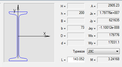
On the left side of the dialog box, select the cross-section of the beam.
Right set sectional dimensions and length L beams. For visual selection of the beam length, click Dynamic input at the bottom of the dialog box.
Enter the physical characteristics of the material and the cut rotation.
Specify moment and the loads acting on the beam.
Setting section
There are three ways to specify the section:
 Standard geometric cross section (e.g., triangle).
 Rolled metal base elements of (e.g, I-beam GOST 8239-89). To use the base when calculating the beams need to set a Class 725.
CAD software Static beam calculation 10 Arbitrary section defined by the user.
Sizing is carried out in several ways:
- Click inside the closed area. Automatically determined by the outer contour of the closed area and the region is added to the set.
- Clicking on a closed polyline or circle. Added to the area bounded by a circle or polyline
- Reselection area removes it from the set for the calculation of the cross section.
After selection of the drawing section in the dialog box Beam calculation appears custom cross-section:

Change the name of the custom section by selecting it and clicking the left mouse button on the title.
Delete a custom section of the list is made by pressing delete.
For the standard section of the database items, choose Type size from the dropdown list.
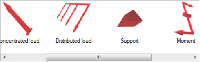
Beam Load and moments
In the dialog box, double-click the desired type of load or moment.
Select insertion point or the load bearing on the beam. At the time of selecting the insertion point move the cursor to the beam to install dependencies.
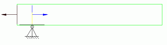
Set the parameters or load bearing in the dialog box.
- Support
Point – the distance from the starting point to the point of insertion beam bearing in millimeters. Use keys to select the type of support.
- Concentrated load
Position – the distance from the starting point to the point of insertion beam load, mm.
Value – the value component of the load in the selected direction, H.
Point – the distance from the insertion point to the point of load application of the load in the selected direction, mm.
Diagram on the left side of the dialog box explains the meaning of the input parameter.
Tabs on the top of the window are used to select the coordinate system in which the values are set:
Rectangular Spherical Cylindrical- Distributed load
Position – the distance from the starting point to the point of insertion beam load, mm.
Length – length of the section, which is attached to a distributed force, KN/mm.
In input fields, set the value component of the load in the selected direction, H.
Diagram on the left side of the dialog box explains the meaning of the input parameter.
Tabs on the top of the window are used to select the coordinate system in which the values are set:
Rectangular Spherical Cylindrical- Moments
Diagram on the left side of the dialog box explains the meaning of the parameters.
X, Y, Z – the components of the bending moment , KN*m.
C – distance from the starting point to the point of insertion beams torque , mm.
Calculation
Click  Calculate beam at the bottom of the dialog box to perform the calculation.
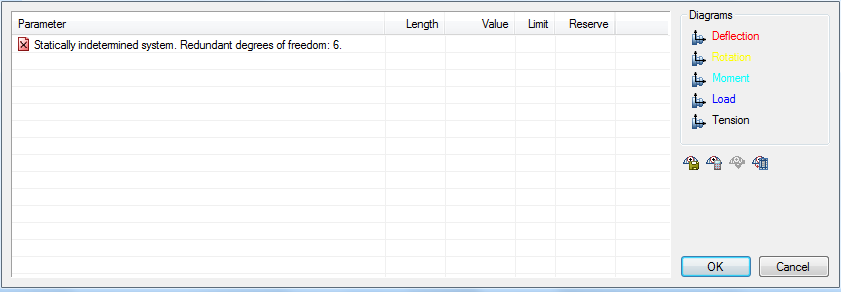
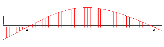
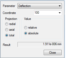
Table of results of calculating comprises calculating the maximum deflection and stress values as well as the distance from the starting point of the beam to a point at which the maximum of each parameter.
To insert a drawing graphs strain and effort to select the desired type of graph for each feature:
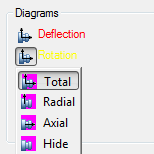 CAD drafting Static beam calculation 24
Apply adds graphics drawing.
Export diagrams. Sell calculation results in a table nanoCAD Construction . After selecting the command, specify the insertion point on the drawing table.
Post your comment on this topic.