
Breaks
 Main menu: Construction – Breaks >
  Break lines.
Ribbon: Construction – Symbols > Break lines.
Toolbar: Breaks > Break lines.
 Command line: SPBREAK.
Procedure
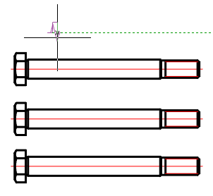
1. Select the first point to insert the break line.
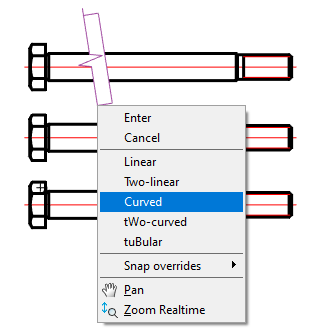
2. In the context menu, select the type of break (break): Linear, Two-linear, Curved, tWo-curved, tuBular.
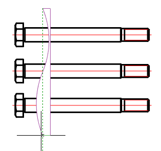
3. Pick the second break point.
4. In the context menu, select the type of cursor movement control: FreeOffset, OrthoOffset.
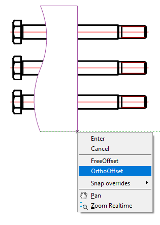
5. Specify the width of the cliff (break). A cliff (break) will be built.
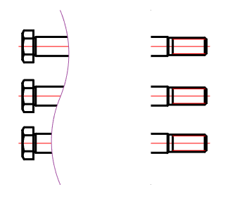
Note:
The whole clipped geometry between the break lines is not actually deleted and can be restored either by removing the break line or editing its contour with the grips nodal points.
Note:
All objects nanoCAD Construction have a so-called Z-Order. This value sets the level of the Z-coordinate in relation to other object-dependent details nanoCAD Construction . Editing the value of the order, you can control the mutual overlap of objects nanoCAD Construction .
Dialogue
The edit dialog is opened from the tooltip when you hover on a break (break) or when you double-click on a break (break).
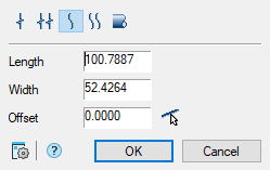
Editing dialog includes:
- Graphic break type switch;
- Field “Length”;
- Field “Width”;
- Field “Offset”. You can get the value using the offset command CAD software Breaks 13“Parallel to specified line”.
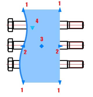
Grips
1. Grips length setting;
2. Grips break width settings;
3. Break displacement grip;
4. Drop-down type grip:
- Linear;
- Two-linear;
- Curve;
- Two-curve;
- Tubular.
Linear break
Main menu: Construction – Breaks >  Linear break.
Ribbon: Construction- Symbols > Linear break.
Toolbar: Breaks > Linear break.
Command line: SPBREAK_LINEAR.
Two-linear break
Main menu: Construction – Breaks >  Two-linear break.
Ribbon: Construction- Symbols > Two-linear break.
Toolbar: Breaks > Two-linear break.
Command line: SPBREAK_TWOLINEAR.
Curved break
Main menu: Construction – Breaks >  Curved break.
Ribbon: Construction – Symbols > Curved break.
Toolbar: Breaks > Curved break.
Command line: SPBREAK_CURVED.
Two-curved break
Main menu: Construction – Breaks >  Two-curved break.
Ribbon: Construction- Symbols > Two-curved break.
Toolbar: Breaks > Two-curved break.
Command line: SPBREAK_TWOCURVED.
Shaft break
Main menu: Construction – Breaks >  Shaft break.
Ribbon: Construction- Symbols > Shaft break.
Toolbar: Breaks > Shaft break.
Command line: SPBREAK_TUBULAR.
Post your comment on this topic.