
Isodraft
Isometric Drafting
 Status bar: ISO button
Toolbar: Isometry – 
Command line: ISODRAFT, -ISODRAFT
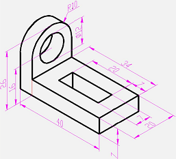
The program contains tools the allow you to draw two-dimensional drawings in an isometric projection. A flat isometric drawing emulates a three-dimensional view of an object from a specific perspective, being, in fact, a flat representation of an isometric 3D-projection.
The isometric drafting tool is convenient to use, when you need to create several simple isometric views in a two-dimensional drawing or edit an existing isometric drawing.
NOTE: a drawing created in the isometric drawing mode are not 3D models. It is impossible to extract 3D distances from them, display in different viewports, automatically suppress hidden lines.
When creating a flat drawing, the isometric projection axes are not orthogonal, which creates significant difficulties when drawing in a usual way, because angles and distances are distorted
Isometric drafting mode
The Isodraft mode is used for isometric drawing.
The Isodraft mode allows you to quickly switch between three isometry planes (isoplanes):
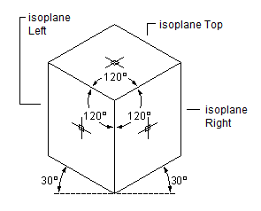
- Isoplane Left. The plane allows you to create objects oriented along the axes of 90 and 150 degrees.
- Isoplane Right. The plane allows you to create objects oriented along axes of 30 and 90 degrees.
- Isoplane Top. The plane allows you to create objects oriented along the axes of 30 and 150 degrees.
![]()
![]()
![]()
![]()
![]()
![]()
![]()
![]()
![]()
![]()
![]()
![]()
![]()
![]()
![]()
![]()
![]()
![]()
![]()
![]()
![]()
![]()
![]()
![]()
![]()
![]()
![]()
![]()
![]()
![]()
![]()
![]()
![]()
![]()
![]()
![]()
![]()
![]()
![]()
![]()
![]()
![]()
![]()
![]()
![]()
![]()
![]()
![]()
![]()
![]()
![]()
![]()
![]()
![]()
![]()
![]()
![]()
![]()
![]()
![]()
![]()
![]()
![]()
![]()
![]()
![]()
![]()
![]()
![]()
![]()
![]()
![]()
![]()
When the mode is enabled, the lines of the cursor crosshairs are aligned in accordance with the axes of the selected isometric plane. While working in isodraft mode, you can switch between isoplanes, which allows you to consistently draw the faces of the target object.

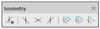
Isometry toolbar
To create isometric drawings, it is convenient to use the Isometry toolbar. It contains the button to enable the isometric drawing mode, three buttons to set isometric planes (ISODRAFT1, ISODRAFT2 and ISODRAFT3 commands), to create isorectangles, isocircles and isoarcs (rectangles, circles and arcs in an isometric projection).
Impact of the mode on drawing settings and precision tools
Enabling (disabling) the isometric drawing mode, as well as setting this or that isoplane changes a number of related drawing parameters and settings, for example, drawing precision tools. The following settings and modes change automatically:
- orthogonal directions;
- snap orientation;
- grid orientation;
- polar tracking angles;
- orientation of isometric circles, arcs and rectangles when they are created.
![]()
Frequently used tools in isometric drawing
In the process of creating isometric drawings, the following construction and precision tools are most commonly used:
- Polar tracking and direction-distance method;
- Object snaps and grid snaps;
- Object tracking;
- Moving and copying;
- Cropping and lengthening.
Enabling isometric drafting mode
The isometric drafting mode is enabled in several ways:
- By -ISODRAFT command;
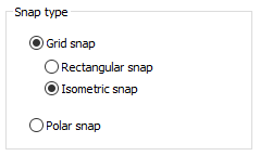
- By isometric snap in the Snap and Grid tab in the Drafting settings dialogue box:
![]()
- Setting 1 as a value for SNAPSTYL system variable;
- Enabling one of isometric planes:
- by selecting one of ISOPLANE options of the ISODRAFT command;
- by selecting one of planes on the Isometry toolbar;
- By the command ISODRAFT1 (isoplane left), ISODRAFT2 (isoplane top), ISODRAFT3 (isoplane right);
- By changing the value of SNAPISOPAIR system variable: 0 – isoplane left, 1 – isoplane top, 2 – isoplane right.
NOTE: to switch quickly between isoplanes, use F5 key.
Creating geometric primitives
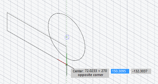
The following commands are used to create circles, arcs, rectangles in the current isometric plane.Creating isocircle
To create a circle in the current plane, use  ISOCIRCLE command that starts the ELLIPSE command with the Isocircle option. If the isodraft mode is disabled at the moment the ISOCIRCLE command is started, then the isometric mode will be enabled first, after which it will be possible to create a circle in the selected isoplane. The Isocircle option of the ELLIPSE command is available only when isometric mode is enabled. When you select the Isocircle option, a circle will be drawn in the current isoplane. The process of drawing a circle in the isodraft mode does not differ from the same action with the disabled isodraft mode: you should specify the center of the circle and select the radius/diameter of the future circle.
Creating isorectangle
To create a rectangle in the current plane, use  ISORECTANGLE command that starts the RECTANGLE command with the Isorectangle option.If the isodraft mode is disabled at the moment the ISORECTANGLE command is started, then the isometric mode will be enabled first, after which it will be possible to create a rectangle in the selected isoplane. The Isorectangle option of the RECTANGLE command is available only when isometric mode is enabled. When you select the Isorectangle option, a rectangle will be drawn in the current isoplane. The process of drawing a rectangle in the isodraft mode does not differ from the same action with isodraft mode disabled: you should specify the point of the first corner of the rectangle and select the point of the diametrically opposite corner/dimensions of the rectangle.
Creating isoarc
To create an elliptical arc in the current isometric plane, use  ISOARC command that starts creating an elliptical arc by the ELLIPSE with the Arc > Isoarc option. If the isodraft mode is disabled at the moment the ISOARC command is started, then it will be enabled first, after which it will be possible to create an arc in the selected isoplane. The Isoarc option of the ELLIPSE command is available only when isometric mode is enabled. When you select the Isoarc option, an arc will be drawn in the current isoplane. The process of drawing an arc in the isodraft mode does not differ from the same action with isodraft mode disabled.
Dimensioning
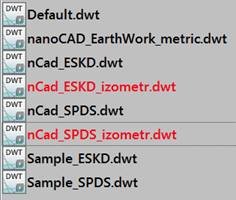
To place dimensions in the isometric drawing mode, it is possible to involve two additional dimension templates (SPDS and ESKD format).
SNAPSTYL system variable
The system variable allows you to change the drawing mode. The variable values are integers:
• 0 – standard drawing mode;
• 1 – isometric drawing mode.
SNAPISOPAIR system variable
The system variable allows you to change the current isometric plane in the current viewport. The variable values are integers:
• 0 – left plane of isometry,
• 1 – top plane of isometry,
• 2 – right plane of isometry.
Post your comment on this topic.