
Visual styles
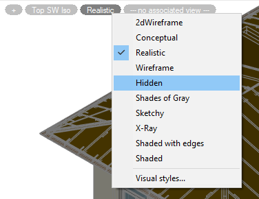
nanoCAD allows you to set methods (styles) for displaying three-dimensional objects in the current viewport. You can change the visual style of a viewport in the Properties bar in Miscellaneous section, or by using the view control widget at the top of the viewport.
nanoCAD allows you to choose the methods (styles) to display the three-dimensional objects in the current viewport. The basic methods of object display:
 |
Wireframe displays the objects using lines and curves to represent the boundaries. The objects are visible. |
 |
Hidden displays the objects using the 3D wireframe representation, but hides the lines representing the back faces. |
 |
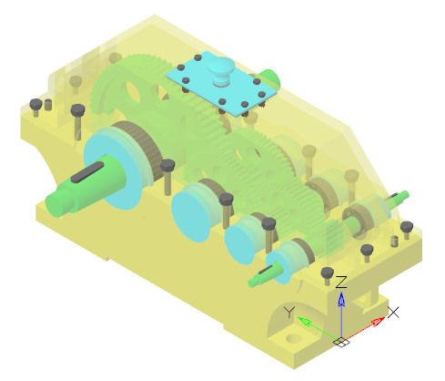
Shade assigns a monochrome color to the visible surface of the object and also makes the background invisible. Each object is shaded by the current color. In the shaded visual styles, the faces are lit by one distant light that is located behind the left shoulder of the user. The object view depends on the selected shading method. |
The command control styles are represented in the View menu – Visual Style.
2D Wireframe
 Ribbon: View – Viewport Tools – Visual Styles >
  2D Wireframe
Menu: View – Visual Style >  2D Wireframe
Toolbar: Visual Style –
 Command line: VSCURRENT0, VS0, VS2DW
Conceptual – objects are displayed using smooth shading and Gooch face style. Gooch’s face style is characterized by transitions between cold and warm, rather than between dark and light shades of colors. This effect is less realistic, but it better represents the model details.
Realistic – objects are displayed using smooth shading and showing materials.
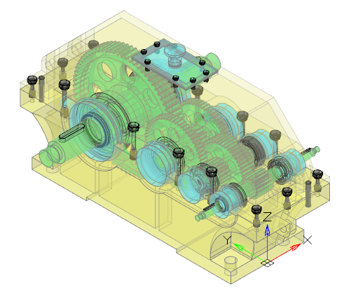
The objects are represented as transparent. The command displays the objects using lines and curves to represent the boundaries. Raster and OLE objects, linetypes, and lineweights are visible.
Features of 2D Wireframe style
2D Wireframe + Top View + DirectX with disable Force using 3D graphics and spatial index combination ignores 3D-coordinates of drawing. It means that incorrect documents with incorrect Z-coordinates will be displayed and processed fast.
NOTE: Use AUDITGEOMETRY command to repair Z-coordinate in incorrect document.
Point Clouds
(color-blue)
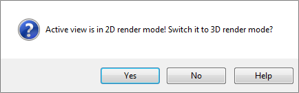
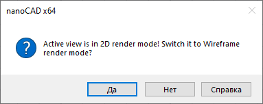
Point clouds doesn’t work in 2D Wireframe style. Select Yes before insert cloud:
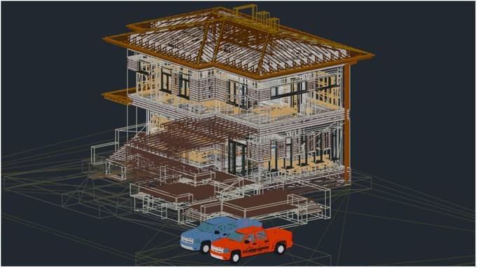
Wireframe
Ribbon: View – Viewport Tools – Visual Styles >  3D Wireframe
Menu: View – Visual Style >  3D Wireframe
Toolbar: Visual Style –
Command line: VSCURRENT1, VS1, VS3DW
The objects are represented as transparent. The command displays the objects using lines and curves to represent the boundaries. Raster objects are invisible, linetypes, and lineweights are ignored.
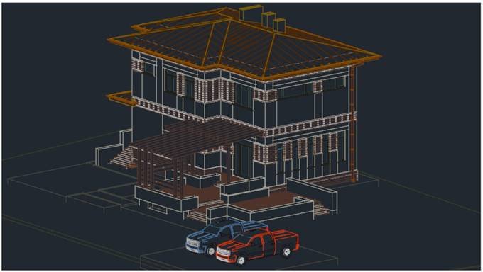
Hidden
Ribbon: View – Viewport Tools – Visual Styles >  3D Hidden
Menu: View – Visual Style >  3D Hidden
Toolbar: Visual Style –
Command line: VSCURRENT2, VS2, VS3DH
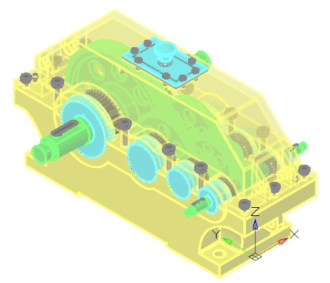
The command displays the objects using the 3D wireframe representation and hides the lines representing the back faces.
Shades of Gray – objects are displayed using shades of a single color (gray) with smooth transitions.
Sketchy – objects are displayed with a freehand drawing effect, taking into account the Line Extend and Jitter edge modifiers.
X-Ray – objects are displayed partially transparent.
Shaded with edges – objects are displayed using smooth shading with visible edges.
Shaded – objects are displayed using smooth shading with no overtly defined edges.
Feature of 2D Wireframe Visual Style
This style is intended for working with flat drawings. Only edges are displayed as lines and curves that represent surface boundaries. Fills and hatches are not displayed. The type and weight of lines are taken into account. Raster and OLE objects are visible.
The 2D Wireframe style settings are not editable in the Visual Styles Dialog Box and cannot be used to create a user defined style.
Work with incorrect z-coordinates
When 2D Wireframe style is used in conjunction with a top view, the z-coordinate values are ignored when displaying and redrawing the drawing. This allows you to quickly display and work with incorrect documents, which are flat drawings, the objects of which have a spread of coordinates in height, often very significant. As a rule, such a spread appears after incorrect conversion of 2D drawings to 3D DWG format by third-party CAD systems. If other visual styles are used, such drawings may take a significant amount of time to display and redraw.
NOTE: To correct (zero) the z-coordinates of objects in such drawings, use the AUDITGEOMETRY geometry check command.
Work with point clouds
2D Wireframe style is not designed to work with point clouds. When importing point clouds into a viewport with 2D Wireframe style set, you will be prompted to automatically switch to Wireframe visual style, which you should accept.
Post your comment on this topic.