
2D Constraints
Aligned
 Main menu: Constraints – Parametrical dimensions –
  Aligned.
Toolbar: Aligned (“Constraints” toolbar).
 Command line: DCALIGNED.
Valid objects and points for the command
- Object control points;
- Line;
- Arc;
- Polyline segment (line or arc);
- Line and control point;
- Two lines.
Operation
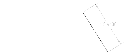
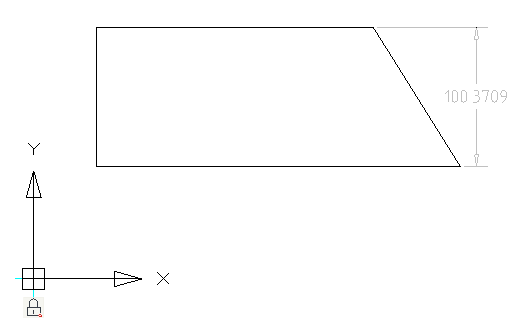
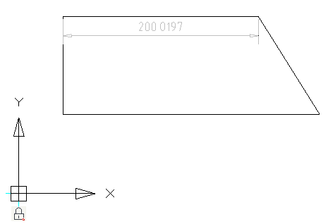
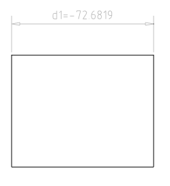
Command sets dimensional constraint for aligned dimensions.
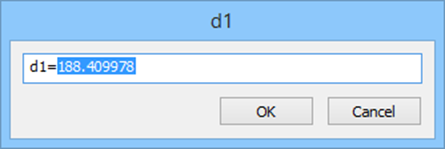
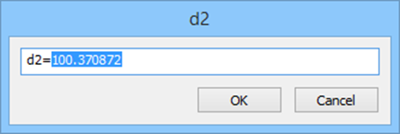
Constraint can be edited. Double-click the dimension to open the editing dialog.
Right-button menu provides select options for easy object selection.
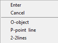
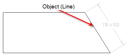
O-object – creates aligned dimensional constraint of the selected object.
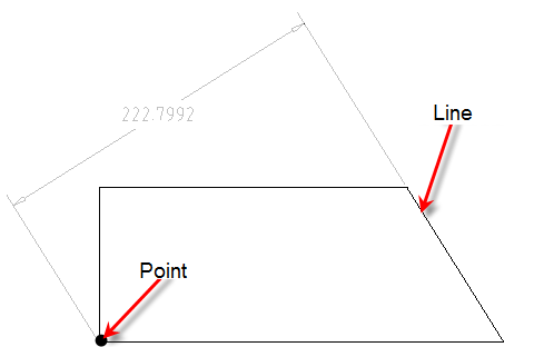
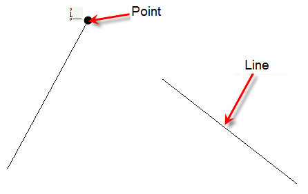
P-point and line – creates dimensional constraint aligned to the normal from a selected point to a selected line.
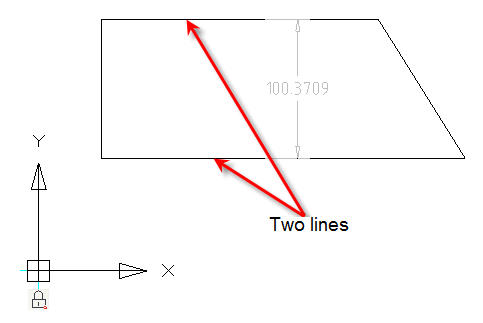
2-2 lines – creates dimensional constraint aligned to normal between two lines.
 .
.
Created constraint can be edited on a planar sketch and via Parameters Manager.
Linear
Main menu: Constraints – Parametrical dimensions –  Linear.
Toolbar: Linear (“Constraints” toolbar).
Command line: DCLINEAR.
Valid objects and points for the command
- Object control points;
- Line;
- Arc;
- Polyline segment (line or arc).
Operation
Sets the linear dimensional constraint on two points. Any two control points can be used (e.g. line or arc end points etc).
Constraint can be edited. Double-click the dimension to open the editing dialog.
Created constraint can be edited on a planar sketch and via Parameters Manager.
O-object – creates aligned dimensional constraint of the selected object.
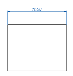
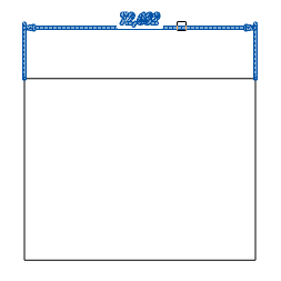
Horizontal
Main menu: Constraints – Parametrical dimensions – Horizontal.
Toolbar: Horizontal (“Constraints” toolbar)
Command line: DCHORIZONTAL.
Valid objects and points for the command
Object control points;
Line;
Arc;
Polyline segment (line or arc).
Operation
Command sets the linear horizontal dimensional constraint on two points. Any two control points can be used (e.g. line end points etc).
Constraint can be edited. Double-click the dimension to open the editing dialog.

Created constraint can be edited on a planar sketch and via Parameters Manager.
O-object – creates aligned dimensional constraint of the selected object.
Vertical
Main menu: Constraints – Parametrical dimensions –  Vertical.
Toolbar: Vertical (“Constraints” toolbar).
Command line: DCVERTICAL.
Valid objects and points for the command
- Object control points;
- Line;
- Arc;
- Polyline segment (line or arc).
Operation
Command sets the vertical dimensional constraint on two points. Any two control points can be used (e.g. line end points etc).
Constraint can be edited. Double-click the dimension to open the editing dialog.
Created constraint can be edited on a planar sketch and via Parameters Manager.
O-object – creates aligned dimensional constraint of the selected object.
Radial
Main menu: Constraints – Parametrical dimensions –  Radial.
Toolbar: Radial (“Constraints” toolbar).
Command line: DCRADIAL.
Valid objects and points for the command
- Circle;
- Arc;
- Arc polyline segment.
Operation
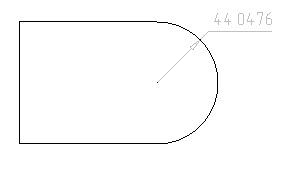
Command sets the radial dimensional constraint on the arc or circle.
Constraint can be edited. Double-click the dimension to open the editing dialog.

Created constraint can be edited on a planar sketch and via Parameters Manager.
Diameter
Main menu: Constraints – Parametrical dimensions –  Diameter.
Toolbar: Diameter (“Constraints” toolbar).
Command line: DCDIAMETER.
Valid objects and points for the command
- Circle;
- Arc.
Operation
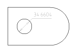
Command sets the diameter dimensional constraint on the arc or circle.
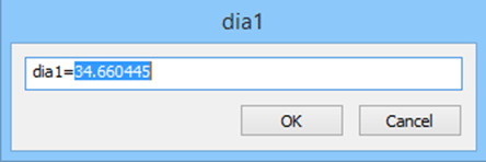
Constraint can be edited. Double-click the dimension to open the editing dialog.
Created constraint can be edited on a planar sketch and via Parameters Manager.
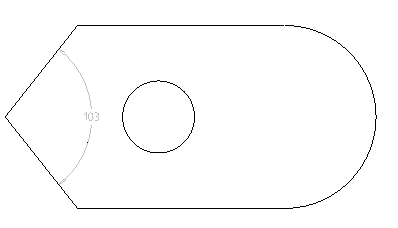
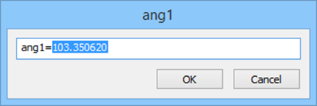
Angular
Main menu: Constraints – Parametrical dimensions –  Angular.
Toolbar: Angular (“Constraints” toolbar).
Command line: DCANGULAR.
Valid objects and points for the command
- two lines;
- line segments of polylines;
- three object control points;
- arc.
The rule for three points selection:
- the first point is a top of the angle;
- the second and the third – end points.
Operation
Command sets the angular dimensional constraint dependence between two lines. It is possible to set an angle by three points.
Constraint can be edited. Double-click the dimension to open the editing dialog.
Created constraint can be edited on a planar sketch and via Parameters Manager.
3-3 points – sets the angular dimensional constraint dependence by three points. Points can belong to different objects.
Dimensional constraint
Main menu: Constraints – Parametrical dimensions –  Dimensional constraint.
Toolbar: Dimensional constraint (“Constraints” toolbar).
Command line: DIMCONSTRAINT.
The command converts simple dimensions to parametric ones.
Operation
1. Create dimensions
2. Call the command and select dimensions to convert
3. Selected dimensions will be converted to parametric ones.
Constraints
Constraints toolbar contains commands to define constraints and parametric relations for geometry of objects on the drawing.

Special icons show assigned constraints and parametric relations for certain geometry elements.
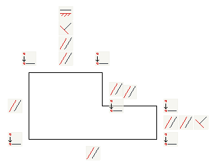
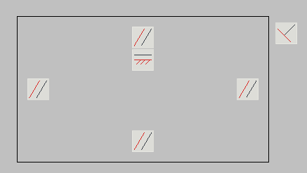
Turn off Show Hatch button  on a Status Bar to hide background for constraints icons.
Coincident
Main menu: Constraints – Geometric –  Coincident.
Toolbar: Coincident (“Constraints” toolbar).
Command line: GCCOINCIDENT.
Valid objects and points for the command
- Object control points;
- Line;
- Circle;
- Arc;
- Polyline segment (line or arc);
- Ellipse.
Operation
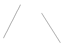
Command coincides two points together. Point which was selected as the second is moved to a point selected first.
Right-button menu of the command’s options:
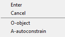
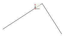
*O-object *- places the selected line that it becomes collinear with the selected point.
A-autoconstrain – automatically assigned constraints to the selected geometry.
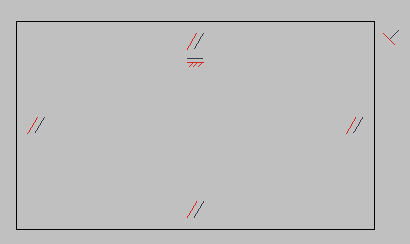
Note: When imposing the Coincident constraint, it is shown by a point, not by an icon. Thus, at one point it may be several overlapping coincident constraints. To remove these dependencies, switch to the Delete constraints mode and move mouse cursor over constraint point. This will unfold the whole set of Coincident at this point. You can remove any of them (see. Fig.)
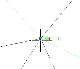 .
.
Collinear
Main menu: Constraints – Geometric – Collinear.

Post your comment on this topic.