
Topographic Hatches
Topographic Hatches
 Ribbon: Topoplan – Situation >
  FillShapes
Menu: Topoplan – Maps > Topographic Hatches
Toolbar: Maps > Topographic Hatches
 Command line: FILLSHAPES
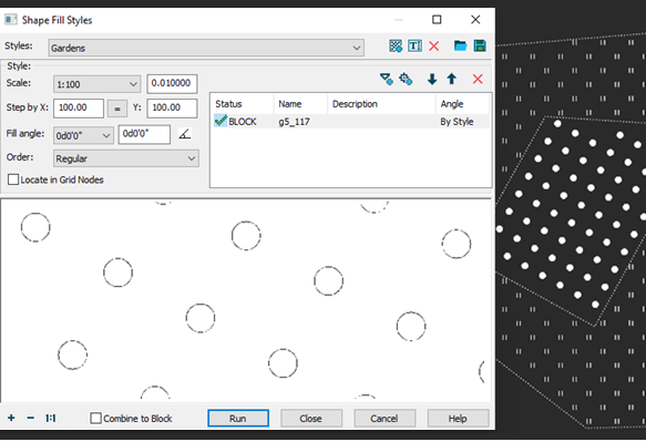
The FillShapes command fills contours with conventional signs on a regular, chess or random grid. Conventional signs can be represented by a combination of blocks from the sign library and SHX shapes.
The command can be used to designate forest areas or wetlands in topographic drawings with conventional signs (CSs). Unlike hatching, the FillShapes command allows you to set the distance between rows and columns of shapes, as well as the rotation angle of the shape in the fill (not to be confused with the rotation angle of the fill itself).
The shape fill does not have associativity; i.e. changing the outline of a filled area (for example, using grips or the Stretch command) does not automatically update the fill.
Options
| Styles | Topographic hatch settings can be saved to styles for later loading and use. In the drop-down list, you can select all styles in the document for editing. · Add Fill Style – create a new style based on the current settings, specifying the name of the new style; · Rename Fill Style – rename the current editable style; · Delete Fill Style – delete the current style; · Load Fill Styles – loading styles into a document from a file (dwg, dxf, dws, dwt); · Save Fill Styles – save styles to a file (dwg, dxf, dws, dwt). |
| Topographic hatch composition | The list of elements of the current topographic hatching. You can add SHX shapes and sign library element blocks as elements.Sometimes there may be a combination of vegetation, soils and farmland in one area. Then it may be necessary to fill the area unevenly with several types of conventional signs (from 2-3 to 4 different types). The order of the element in the list determines the order in which it is placed in the hatch. You can change the order of elements in hatching using the CAD drawing Topographic Hatches 14 CAD drafting Topographic Hatches 15 buttons by moving the element up or down in the list. The CAD software Topographic Hatches 16 button can be used to remove an element from the current hatch. |
| Add Shape | Adding an SHX shape as a hatch element. Opens the Choose Shape dialog where you can select the desired shape from the existing SHX files.SHX files are located in the folder specified in the Default directories section of the Options dialog. |
| Add Block | Adding a block as a hatch element. In order to display all CS blocks of the Conventional Signs bar in the dialog, first insert at least one conventional sign into the drawing. You can search for a block by entering in the search field the numerical designation of the block: alphabetic description, or even block size values displayed in square brackets in the current units after the alphabetic description: |
| Scale | The scaling factor for the size of hatch signs |
| Step by X | Horizontal offset distance of hatch elements |
| Y | Vertical offset distance of hatch elements. |
 |
Copies the X step to the Y box |
| Fill angle | Angle of hatch rotation. You can select the desired angle value among the fixed ones from the drop-down list, enter your own angle in the field using the keyboard, or specify the angle on the drawing after pressing the CAD software Topographic Hatches 25 button. · 0 degrees: · 30 degrees:· 90 degrees: |
| Order | The principle of alternating elements relative to each other. · Regular hatching order of three elements · Chess order of the same hatching elements The chess order of filling with signs is usually used to designate grass vegetation, nursery farms, agricultural lands. · Random order the hatching elements The irregular order of filling with signs is used in the designation of all types of natural origin forests. |
| Locate in Grid Nodes | Ignores some previous settings and places hatch elements at grid nodes. The step is taken from the grid step specified in the Drafting Settings dialog. Rotation angle = 0. |
| Combine to Block | Allows you to create a single block from all the elements that make up the fill. The block can later be split into separate objects with the Explode command. |
After setting all the hatching parameters, press the Run button and click inside all the closed contours to be filled.
Info: NanoCAD is an easy-to-use, cheap, and yet professional, CAD app for personal computer, that provides an outstanding user experience by providing top-level performance, full capability, a classic interface and native.dwg format support. nanoCAD has been built to deliver design and project documentation for all industrial purposes. nanoCAD includes a full suite of basic and advanced CAD tools for 2D/3D drawing and creating industry-standard DWG-compatible CAD files. Our program provides progressive, collaborative and customizable features to enhance your efficiency, and includes a few API’s, allowing anything from routine task automation to complex CAD application development. You may download nanoCad for free, using the links below, and buy later, in case you like it.
Post your comment on this topic.