
Edit references
 Ribbon: Insert – Reference >
  Edit reference
Menu: Tools – External reference > Edit reference
 Command line: REFEDIT
The use of external references allows you to quickly combine multiple drawings in a single document. To make work with external references more convenient, you can edit the references directly in the current drawing to which they are added.
To edit a referenced drawing from within the current drawing, you should use the working set to identify objects that belong to the external reference or block insertion rather than the current drawing. The working set includes only the objects belonging to the reference selected for editing.
You can add or remove objects from the working set. If you create a new object while editing a reference, it is almost always added to the working set automatically. Editing changes in the working set can be stored in the source file of the external reference or block insertion.
Start the Edit reference command. In the command line you can see:
Select reference or block insertion or [All insertions]:
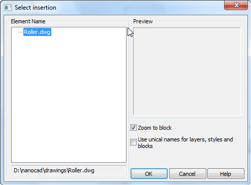
Select the external reference on the drawing and in the Select insertion dialog box that opens, choose the objects to edit:
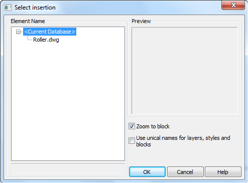
If you select the All insertions option in the command line, the Select insertion dialog box opens immediately and in the Element Name section all references and blocks inserted into the drawing will be displayed:
Parameters:
| Zoom to block | Switches on/off the mode to display the selected reference on the screen. |
|---|---|
| Use uncial names for layers, styles and block | Controls whether layers and other named objects extracted from the reference are uniquely altered. If selected, named objects in external references are altered (names are prefixed with $#$), similar to the way they are altered when you bind external references. If cleared, the names of layers and other named objects remain the same as in the reference drawing. Named objects that are not altered to make them unique assume the properties of those in the current host drawing that share the same name. |
Select the objects for editing and click OK. The Refedit toolbar will appear automatically.
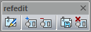
Use the Refedit toolbar to add or remove objects from a working set and also save and discard external reference editing.
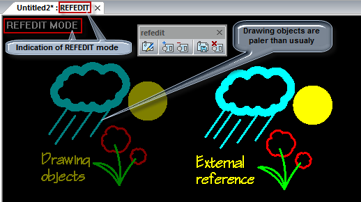
REFEDIT, separated by a colon, is added to the document name in the tab and “Refedit mode” is shown in the top left corner of the working area. It means that work with the document occurs in the external reference editing mode.
ATTENTION! In edit references mode you MUST NOT (!) close neither a document with edited reference nor nanoCAD till all changes are saved or discarded (Save and Close or Discard and Close buttons on the Refedit toolbar).
After saving or discarding all changes the Refedit toolbar closes and a document tab returns to its original view.
Add objects to the working set
Menu: Tools – External reference >  Add objects to working set
Toolbar: External Reference –
Command line: REFSET
Use this command to transfer the objects from the current drawing to the working set.
Remove objects from the working set
Menu: Tools – External reference >  Remove objects from working set
Toolbar: External Reference –
Command line: REFSET
Use this command to remove selected objects from the working set.
Save external reference changes
Menu: Tools – External reference >  Save and close
Toolbar: External Reference –
Command line: REFCLOSES
Use this command to save external reference changes and close the refedit toolbar. The external reference editing mode will be completed. The REFEDIT term, separated by a colon, that was added to the document name in the tab will disappear.
Discard external reference changes
Menu: Tools – External reference >  Discard changes
Toolbar: External Reference –
Command line: REFCLOSED
Use this command to discard external reference changes and close the External Reference toolbar. The external reference editing mode will be completed. The REFEDIT term, separated by a colon, that was added to the document name in the tab will disappear.
Info: NanoCAD is a user friendly, cheap, and yet professional, CAD software tool for PC, that provides an outstanding user experience by providing top-level performance, full capability, a classic interface and native.dwg format support. nanoCAD has been built to deliver design and project documentation for all industrial purposes. nanoCAD includes a full suite of basic and advanced CAD tools for 2D/3D drafting and creating industry-standard DWG-compatible CAD files. Our program ensures groundbreaking, collaborative and customizable features to enhance your efficiency, and includes several API’s, allowing anything from routine task automation to complex CAD app development. You may download nanoCad for free, using the links below, and purchase later, in case you like it.
Post your comment on this topic.