
 Ribbon: Raster – File >
  Insert Image
Ribbon: Insert– Reference > Insert Image
Menu: Insert –  Image from file…
Menu: Raster – Image from file…
Toolbar: Draw –
 Command line: IAT, IMAGEATTACH, ROPEN, INSERTRASTER
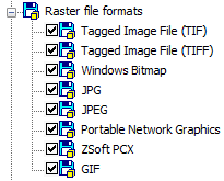
You can insert images into the drawing. The list of supported raster formats is displayed in the Raster file formats section of the Options dialog box (the Tools menu– Options):
Raster images can be referenced and placed in drawing files but, like external references, they are not actually part of the drawing file. The image is linked to the drawing file through a path name. Linked image paths can be changed or removed at any time.
Once you’ve attached an image, you can reattach it multiple times, treating it as if it were a block. Each insertion has its own clip boundary and its own settings for brightness, contrast, fade, and transparency.
You can insert in the drawing a number of raster image files with the same name but different content. In such a case, a sequence number will automatically be added to the names of such images via an underscore sign “_” starting with 1.
To insert a raster image, specify the necessary options in the opened Insert Raster Image dialog box.
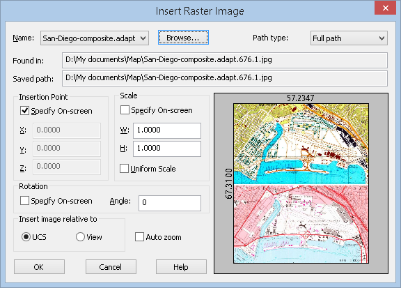
Parameters:
Name:
Includes the list of names of the inserted images.
 Opens the Insert Raster Image dialog box.
Path type:
Sets the way to describe the location of the source file for the raster image insertion. Dropdown list contains several variants:
- Full path (absolute);
- Relative path;
- No path.
For more information on specifying a path, see the Insert External Reference section.
Insert Point
Specify On-screen Select the box to set the X,Y,Z coordinates values in the command line or specify the position on the screen. The «X» «Y» «Z» fields of this section are inaccessible.
X: Y: Z: Enter the X, Y, Z coordinate values for the raster image insertion in the corresponding fields..
Scale
Specify On-screen Select the box to set the scale value of the raster image in the command line or specify the position on the screen.
The «X» «Y» «Z» fields of this section are inaccessible.
W: Set the scale factor width.
H: Set the scale factor height
Uniform Scale Specifies the scale factor for the Width or Height values. A value specified for Width is also reflected in the Height value.
Rotation
Specify On-screen Specifies the rotation angle for the inserted image, using the pointing device.
Angle: Sets the rotation angle for the inserted image.
Insert image relative to
UCS Sets the insert image mode relative to the User Coordinate System (UCS).
View Sets the insert image mode relative to the World Coordinate System (WCS)
Auto zoom Switches on/off the full screen mode of the inserted reference
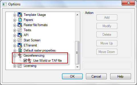
.To insert georeferenced raster image, check Use World of TAF file in Options dialog.
Info: NanoCAD is an easy-to-use, cheap, and yet powerful, CAD platform for PC, that delivers an outstanding user experience by providing top-level performance, full capability, a classic interface and native.dwg format support. nanoCAD has been built to deliver design and project documentation for all engineering purposes. nanoCAD includes a full suite of basic and advanced CAD tools for 2D/3D drawing and creating industry-standard DWG-compatible CAD files. Our program ensures innovative, collaborative and customizable features to boost your efficiency, and includes a few API’s, allowing anything from routine task automation to complex CAD software development. You may try nanoCad for free, using the links below, and buy later, in case you like it.
Post your comment on this topic.