
Create TIN by points
 Ribbon: Topoplan – Create TIN >
  Create TIN by points
Menu: Ground – Creating TIN >  Creating a TIN by points
Toolbar: Creating TIN > Creating a TIN by points
 Command line: NG_CREATE_TIN
The command creates a TIN (Triangular Irregular Network) surface – an irregular triangulation network by point objects represented by Points, Geopoints or Blocks. The following objects can be created: SubMesh, Polyface mesh, Solids or 3D Faces.
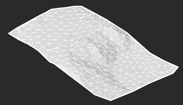
A set of points for creating a mesh can be obtained by importing from third-party formats or from a point cloud with the Explode the Cloud into Points command.
Options
| Result type values | PolyFace mesh – creates an object of Polyface mesh type, the nodes of which can be edited;
|
|---|---|
| Filtrate source points | You can change the number of points that will be used to build create triangulation. To do this, select Yes for the Filtrate source point option, select the type of filtration for Filter Units parameters and set the desired value in the Filter range field. This will create a mesh with fewer number of larger triangles. This accelerates the process of creating a triangulation model. The created model will be less accurate, but its further processing will take less time. The following filtration types are possible:
|
| Build boundary from convex hull | When this option is enabled, after creating the triangulation the mesh will be processed. Triangles with an edge length greater than the specified one will be removed. The length value is specified in the Max edge field. The length is specified as a percentage of the maximum edge units of the face in a triangulation model or in drawing units (based on the value of Max edge units parameters) |
| Only external boundary | When this option is enabled, only triangles located at the mesh edges will be removed during the mesh processing. |
| Project points to UCS XY plane | When this option is enabled, the triangulation will be created in the XY plane of the user coordinate system. When the option is disabled, the triangulation will be created in the plane of the current view. |
| Select region | It is used when you need to build a model not by all points, but only by a certain part. In this case, click the button to the right of the Region is not selected value and draw a polygonal area within which the triangulation will be created on the point cloud. |
| Generate normals | Shading parameter. Calculates normals at the mesh vertices, resulting in a smoother mesh appearance in the Precise view. The option is available only if a mesh is selected as the resulting triangulation object. |
| Use point color | Colors the faces and vertices of the mesh according to the points color. The option is available only if a mesh is selected as the resulting triangulation object. |
| Break for optimization | If the triangulation model turns out to be very detailed (millions of faces), then for the possibility of further convenient work, it will be divided into several meshes. If the parameter is disabled, the model will not be split, a single mesh will be created. |
| Filter by layer | The possibility to create a surface only by objects of a certain layer. When you select Yes in the drop-down list, it is necessary to specify the layer. |
| Create layer | When you select Yes, the mesh will be created on a new layer TIN surface. |
Command prompts:
Apply changes? or [Yes/No]:
- Yes – TIN will be created with the current settings.
- No – if the settings have been changed, they are not saved. TIN will be created with the settings displayed immediately after starting the command.
Info: NanoCAD is an easy-to-use, low cost, and yet professional, CAD software tool for Windows, that allows an outstanding user experience by providing enhanced performance, full capability, a classic interface and native.dwg format support. nanoCAD has been built to deliver design and project documentation for all engineering purposes. nanoCAD includes a full suite of basic and advanced CAD tools for 2D/3D design and creating industry-standard DWG-compatible CAD files. Our software supports progressive, collaborative and customizable features to improve your efficiency, and includes a few API’s, allowing anything from routine task automation to complex CAD software development. You may try nanoCad for free, using the links below, and purchase later, in case you like it.
Post your comment on this topic.