
Selecting data in raster images
![]() This functionality is available only in the Raster module.
This functionality is available only in the Raster module.
 This functionality is available only in the Raster module.
To edit the content of monochrome raster images, apply the raster selection. Using various types of selection, you can select on raster images:
- raster objects – raster lines, arcs and circles;
- areal fragments of a raster image;
- rasterlinessegments – fragments of raster lines of any shape limited by points of intersection with other raster lines or endpoints;
- isolated raster fragments – multiple interconnected raster points.
The order of raster selection
- set the selection mode: add data to selection, remove from selection, single selection;
- run one of the selection methods: specifying, within the rectangle, clipping polygon, etc. The selection method is assigned based on the type of raster data being selected;
- carry out the procedure for pointing on the image in accordance with the running method.
Quantitative raster selection modes
 Ribbon: Raster– Raster Selection – Basic methods > …
Menu: Raster – Raster Select > …
| Button | Mode | Action |
|---|---|---|
 |
Single | Each new selection cancels the previous selection |
 |
Remove | The selected data are excluded from the existing selection. |
 |
Add | New raster data are added to the selection set. |
 |
Select All | The content of all raster images is selected. |
 |
UnSelect All | All data are unselected. |
Basic selection modes
Ribbon: Raster– Raster Selection > …
Menu: Raster – Raster Selection > …
| Button | Method name | Specifying procedure | Selected raster data |
|---|---|---|---|
 |
Select Auto | Specify the object. | Raster object. |
 |
Select by rectangle (rectangular area) | Specify opposite corners of rectangular area. | All raster data inside the rectangular area. The selection border runs exactly along the edge of the rectangular selection box. |
 |
Select by polygon (polygonal area) | Specify points that determine the boundary of a polygonal area that completely covers the selected data. Press ENTER. | All raster data are polygon-bound. The selection border runs exactly along the edge of the polygonal selection box. |
 |
Select Raster Line | Specify two points – the ends of the reference line. | Raster line below the reference line |
 |
Select Raster Arc | Set three points – start, arbitrary midpoint, and end point of the reference arc. | Raster arc below the reference arc. |
 |
Select Raster Circle | Specify two points – the ends of the reference circle diameter. | Raster circle below the reference circle. |
 |
Select Raster Flood Fill | Specify any point on a raster object | Parts of an image whose raster points touch each other.This is useful for selecting isolated raster objects. |
Object raster selection methods
The trace selection of raster data is based on the principle of recognition of individual raster objects: raster lines, arcs and circles in the selected area or on its border.
 |
Inside window | Specify opposite corners of the rectangular area. | Objects that are completely within the rectangle. Raster objects crossed by the rectangle border are not selected. |
 |
Inside polygon | Specify points that determine the boundary of the polygonal area. Press ENTER. | Specify points that determine the boundary of the polygonal area. Press ENTER. |
 |
Specify points that determine the boundary of the polygonal area. Press ENTER. | Specify points that determine the boundary of the polygonal area. Press ENTER. | Objects that are inside the polygon, as well as all raster objects crossed by the polygon boundary. |
 |
Cross polygon | Specify points that determine the boundary of the polygonal area. Press ENTER. | Objects that are inside the polygon, as well as all raster objects crossed by the polygon boundary. |
 |
Fence | Specify a set of points – polyline vertices. Press ENTER. | Raster objects crossed by the specified line. |
Trace selection methods.
Trace selection of raster data is based on the principle of recognizing raster line segments in a given area or before crossing with other segments.
| Button | Method name | Specifying procedure | Selected raster data |
|---|---|---|---|
 |
Inside window (trace) | Specify opposite corners of the rectangular area | Objects that are completely within the area before crossing with other segments. Raster objects crossed by the rectangle border are not selected. |
 |
Inside polygon (trace) | Specify points that determine the boundary of the polygonal area. Press ENTER. |
Fill Selection Methods
| Button | Method name | Specifying procedure | Selected raster data |
 |
Inside window (fill) | Specify opposite corners of the rectangular area | Objects that have contacting pixels and are completely within the rectangle. |
 |
Inside polygon (fill) | Specify points that determine the boundary of the polygonal area. Press ENTER. | Objects that have contacting pixels and are completely within the polygon. |
 |
Cross window (fill) | Specify opposite corners of the rectangular area | Objects inside the area, crossed by the rectangle border and all contacting areas. |
 |
Cross polygon (fill) | Specify points that determine the boundary of the polygonal area. Press ENTER. | Objects inside the polygon and crossed by the polygon border and all contacting areas |
 |
Fence (fill) | Specify a set of points – polyline vertices. Press ENTER. | Raster objects crossed by the specified line and all contacting ones. |
The fill selection of raster data is based on the principle of recognition in a given area of contacting (merging) raster points.
Setting Selection OptionsFor correct recognition of raster objects when using the object selection methods, it is necessary to make settings in the Options tab of the Conversion options dialog box:
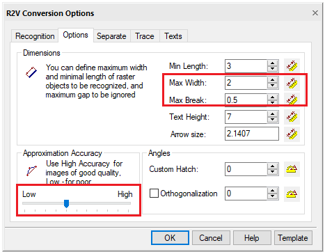
Selection options for recognizing raster objects
| Option | Description |
| Max. width | The maximum thickness of raster objects that can be selected using object recognition or line-following methods. Lines that are thicker than the specified value will not be selected. |
| Max. break | The amount of the maximum ignored raster line break. If the raster line breaks are less than the specified value, the line will be selected as a single object |
| Approximation Accuracy | When a raster is selected using methods based on object recognition, the Accuracy parameter sets the acceptable degree of deviation of the shape of raster entities from their vector prototypes. If the original raster entities are distorted, for example, the raster circles are elliptical, the selection accuracy will increase as you move the Accuracy slider to the left. To make a selection on the original raster image of good quality, move the slider to the right. |
The values of Max. thickness and Max. break parameters can be measured in a raster image using  buttons next to the fields.
Info: NanoCAD is a simple, inexpensive, and yet powerful, CAD software tool for PC, that delivers a great user experience by providing high performance, full capability, a classic interface and native.dwg format support. nanoCAD has been built to deliver design and project documentation for all engineering purposes. nanoCAD includes a full suite of basic and advanced CAD tools for 2D/3D drafting and creating industry-standard DWG-compatible CAD files. Our software provides innovative, collaborative and customizable features to enhance your efficiency, and includes a number of API’s, allowing anything from routine task automation to complex CAD application development. You may download nanoCad for free, using the links below, and buy later, if you like it.
Post your comment on this topic.