
Add structure line
 Ribbon: Topoplan – Modify TIN >
  Add Structure Line
Menu: Ground – Editing TIN >  Add Structure Line
Toolbar: Editing TIN > Add Structure Line
 Command line: NG_MESH_STRUCTURAL_CREATE
The command adds a new structure line to the existing surface.
Structure lines are used to detail relief forms. Such lines can describe lines of curbs, pavement boundaries, gulleys, watersheds, etc. When there are structure lines present, the surface triangulation is forced along the structure line; triangulation edges cannot intersect a structure line. Types of objects that can be added as structure lines: lines, polylines, 3D polylines.
To add a structure line:
- Run the command.
- In response to the prompt in the command line:
Project profile on or [WCS/UCS/Viewport]:
WCS – a polyline will be projected on the XY plane of the world CS;
UCS – a polyline will be projected on the XY plane of the user CS;
Viewport – a polyline will be projected on the viewport plane.
- In response to the prompt
Select polyline or line to be added as structural line or [?]:
specify a line, polyline or 3d polyline. After selecting an object by the cursor, triangulation will be rebuilt.
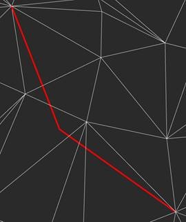
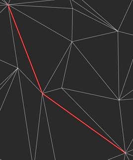
Surface before adding a structure line  Surface after adding a structure line
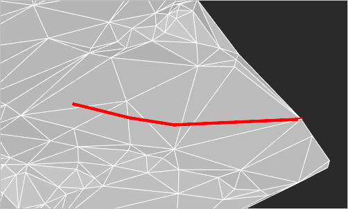
To add a Retaining wall structure line:
1. Run the command.
2. Configure the parameters in the Properties bar. The Structure type should have the Retaining will value. Press ENTER in response to the prompt in the command line:
Apply changes? or [Yes/No]:
3. In response to the prompt
Select polyline or line to be added as a structural line or [?]:
specify a line, polyline or 3d polyline.
4. In response to the prompt
Specify the side of the wall offset:
specify the slope side.
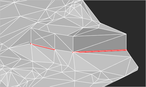
5. If the Set the wall height parameter was set to Separate vertices, then specify the wall height for each line vertex. The current vertex is indicated by a red circle.
The mesh triangulation will be rebuilt. The retaining wall is always vertical in the World coordinate system.
Info: NanoCAD is a user friendly, cheap, and yet professional, CAD program for personal computer, that delivers a great user experience by providing enhanced performance, full capability, a classic interface and native.dwg format support. nanoCAD has been built to deliver design and project documentation for all engineering purposes. nanoCAD includes a full suite of basic and advanced CAD tools for 2D/3D drawing and creating industry-standard DWG-compatible CAD files. Our program ensures groundbreaking, collaborative and customizable features to boost your efficiency, and includes a few API’s, allowing anything from routine task automation to complex CAD application development. You may try nanoCad for free, using the links below, and buy later, if you like it.
Post your comment on this topic.