
Cell Properties dialog
The parameters of table cells are set in the Cell properties dialog box.
To edit the properties of a single cell:
1. Select the required cell in the Table edit dialog box.
2. Select the Properties command from the right-button menu or use the Ctrl + Enter key combination or double click on the cell.
NOTE: The action of this command is similar to Cell Properties on the Table edit toolbar.
To edit several table cells:
1. Select the required cells.
2. Select the Properties command from the right-button menu or use the Ctrl + Enter key combination or double click on the cell.
NOTE: The effect of this command is similar to Cells Properties on the Table edit toolbar.
There are six tabs:
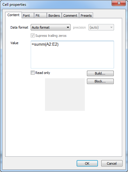
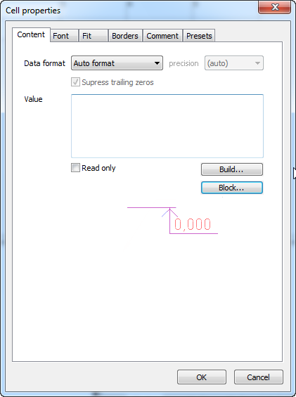
- In the Content tab you can specify the data format and formula to calculate a value:
![]()
You can specify the data format and enter the value for the cell. Select the Read only checkbox to prevent cell editing. Such cells are highlighted.
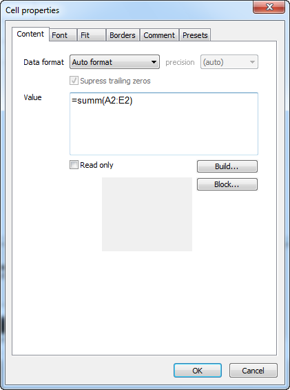
![]() – Opens the Expression builder.
– Opens the Expression builder.
![]()
![]() – Insert block into the cell.
– Insert block into the cell.
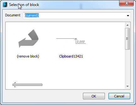
Select a block in the current drawing. You can select another file using Open menu
![]()
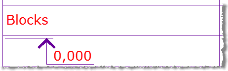
After block selection, it is displayed in the cell properties dialog box and in the table cell.
![]()
![]()
To detach a block, select Remove block in the Selection of block dialog box.
![]()
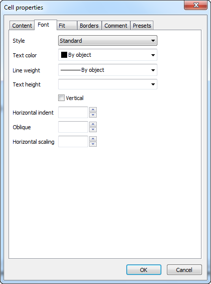
- In the Font tab you can specify text font, symbol color, line weight, indent, text angle and text scaling.
![]()
The Vertical checkbox changes the text direction to vertical.
If the Oblique and Horizontal scaling fields are empty, their values are taken from the text style. If the Horizontal indent field is empty, its value is taken from the table settings. - In the Fit tab you can specify cell width and height and fitting parameters.
![]()
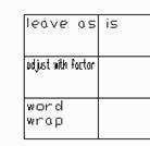
If text width is more than cell width:
![]()
If text height is more than cell height:
![]()
 – Opens the Expression builder.
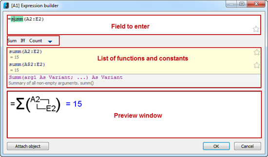
 – Insert block into the cell.
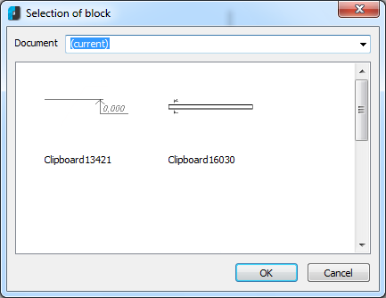
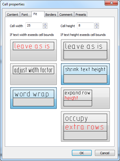
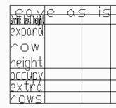
Occupy extra rows does not change the row’s number in the table, the required row is made higher by the required number of times and lined.
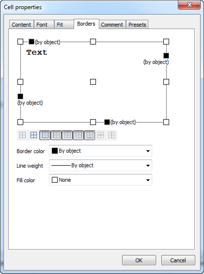
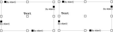
- In the Borders tab you can specify the type, weight and color of the lines of the selected cell. You can control the display of cell borders. To switch border display on/off, select one of the buttons:
![]()
![]()
Or click near the cell border in the preview area. To align text in the cell, click the…… symbol in the cell.
![]()
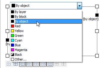
To specify the color of the border, click the symbol .. and select a color from the list.
![]()
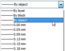
To specify the line weight of the border, select the Line weight field and select the weight from the list.
![]()
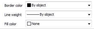
The color and weight of cells and their fill color can be specified in the tab.
![]()
To apply a new color and weight, click the border or use the buttons.
![]()

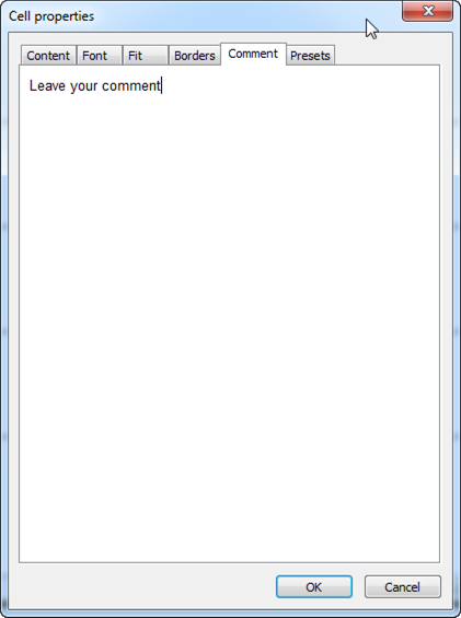
- Comment tab. Field to enter a comment.
![]()
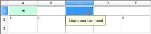
A cell with a comment is displayed with a green label in the editor and when moving the cursor over it the comment is shown.
![]()
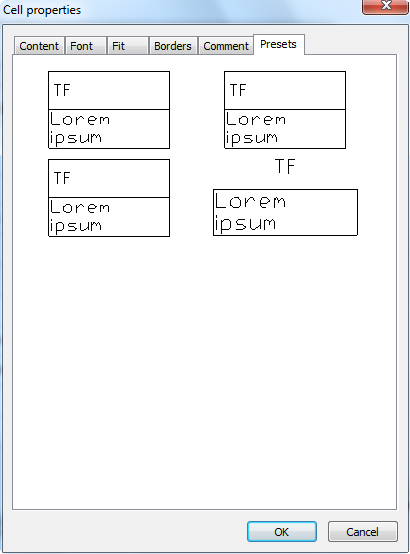
- In the Presets tab you can specify the style for a cell.
![]()
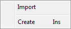
To create a style, click on an empty space on the Presets tab and from the context menu select Create.
![]()
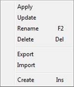
To work with style templates, open the context menu of a style.
![]()
Snap to cell
In every cell formula you can use other object properties. If automatic table recalculation is switched on, the object formula is automatically recalculated when the object is changed. You can attach one or several objects to every cell. Objects have names: Object1, Object2, Object3 … There is continuous numbering in the table. If an object is not used in any formulas, it is detached from the table during the following recalculations and the object references are renumbered.
To snap object properties to a specified cell, use Expression from the right-button menu or press the key combination Shift + F2
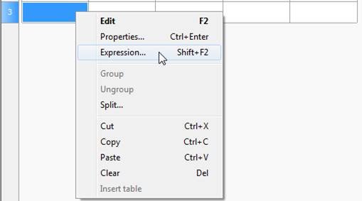
The Expression builder dialog box opens
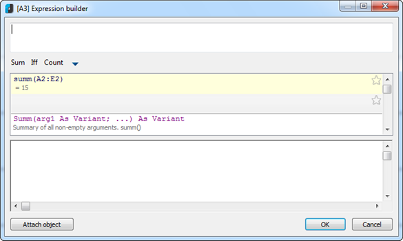
Click the Attach object button.
Select the object whose properties you want to snap to the cell. In the properties list you will see the selected object’s properties. Double-click it and the property will be added to the cell field. Click OK.
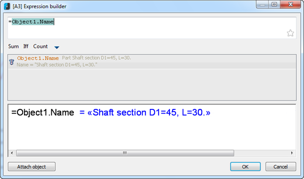
After the object is attached to the cell, the cell color is changed (it means that there is a formula in the cell) and the calculated result will be displayed:

Info: NanoCAD is a user friendly, affordable, and yet powerful, CAD freeware tool for PC, that provides a great user experience by providing top-level performance, full capability, a classic interface and native.dwg format support. nanoCAD has been built to deliver design and project documentation for all industrial purposes. nanoCAD includes a full suite of basic and advanced CAD tools for 2D/3D drawing and creating industry-standard DWG-compatible CAD files. Our tool supports groundbreaking, collaborative and customizable features to enhance your efficiency, and includes a few API’s, allowing anything from routine task automation to complex CAD app development. You may try nanoCad for free, using the links below, and purchase later, if you like it.
Post your comment on this topic.