
Calibration
 Ribbon: Raster– Modification>
  Calibration
Menu: Raster–  Calibration
 OK Command line: CALIBRATION
 This functionality is available only in the Raster module.
The calibration operation affects the entire image. When multiple images are selected, the command is applied to visible images located on unlocked layers.
The calibration transformation is determined by the transformation model and a set of calibration pairs.
When preparing calibration, it is necessary to specify the vectors of raster points displacement. To do this, specify a set of calibration pairs. Each of these pairs determines two coordinates – the current position of a point on the image (measured point) and its required theoretical position (real point).
A transformation model is a type of parametric transformation used in calibration. Each model determines a family of transformations of the same type.
When using some sets of calibration pairs and individual methods, the program is not able to perform the transformation of a given type in such a way that all measured points move to the corresponding real points. This leads to deviation of the points obtained as a result of transformation from the corresponding real points. The criterion for choosing the conversion parameters is to minimize the root-mean-square error at all calibrated points.
Each of the calibration pairs is one of the following types:
- Grid – if a pair is part of the calibration grid; used in calculating the calibration parameters and assessing the calibration accuracy;
- Check – if a pair is used when calculating the calibration parameters and assessing the calibration accuracy;
- Control – if a pair is used only to assess the calibration accuracy and does not affect the calibration parameters;
- Unused – if a pair is not used when calculating the calibration parameters and assessing the calibration accuracy.
Basic Calibration steps
1. run the calibration command;
2. create a set of calibration pairs;
3. specify the position of measured points;
4. choose a suitable calibration method;
5. calibrate.
Before performing the calibration, it is recommended to set the coordinate system – origin and scale.
Calibration command
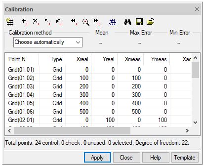
The command opens the calibration dialogue box.
Calibration dialogue button
| Button | Description |
 Define grid Define grid |
Creates a set of calibration pairs located at the nodes of a rectangular grid |
 Add point Add point |
Creates a calibration pair using a dialogue box |
 Modify point Modify point |
Allows you to change the location of the measured and real points, as well as the type of selected calibration pair |
 Reset point Reset point |
Moves measured points to real points position for selected calibration pairs |
 Delete point Delete point |
Removes all selected calibration pairs from the list and their corresponding points in the drawing |
 Previous point Previous point |
Pans the drawing to show the previous calibration pair in the center of the screen |
 Zoom to point Zoom to point |
Pans the drawing to show the selected calibration pairs in the center of the screen |
 Next point Next point |
Pans the drawing to show the next calibration pair in the center of the screen |
 Estimate Estimate |
Estimates calibration accuracy |
Specifying a set of calibration pairs
When creating calibration pairs, their definitions are added to the list in the Calibration dialogue box:
1. Specify the known theoretical coordinates of points (real points) in one of two ways: by specifying a calibration grid or adding points one by one, or both at the same time. When created, each calibration pair has the same coordinates of measured and real points;
2. Set the corresponding measured points for all real points by selecting them in the image or by entering their coordinates from the keyboard.
Setting the calibration grid
When specifying a calibration grid, it creates a set of calibration pairs, the points of which are located at the nodes of a rectangular grid. Such calibration pairs relate to the Grid type.
The position of the calibration pair points specified when creating a grid is determined by the origin of the grid, the cell size, and the number of cells in the horizontal and vertical directions.
There can be only one grid in a calibration object. Re-setting the calibration grid will delete all calibration pairs belonging to the existing grid.
Click the Define grid button
The Calibration grid dialogue box appears:
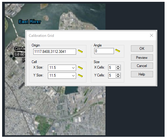
1. Specify the calibration grid origin;
2. Enter coordinates in the Origin field or click the Choose origin button and specify with the mouse the location of the grid origin in the image. The bottom left corner of the grid is taken as the grid origin, and the grid is generated in the positive direction of X and Y axes;
3. Set cell dimensions along X and Y axes;
4. If necessary, you can also add columns in the negative direction of X or Y axes by specifying a negative value for the X or Y dimensions;
5. Specify the number of cells along X and Y axes using the Х cells and Y cells respectively;
6. To avoid errors, click the Preview button and view the specified grid. If necessary, correct errors;
7. Select OK to create a calibration grid and return to the Calibration dialogue box.
You can create a rectangular grid rotated by a specified angle. Otherwise, the grid rows and columns will be orthogonal to the X and Y axes.
Setting the calibration grid through the loaded file
To add an arbitrary calibration grid, it is possible to create a text file with the RPT extension. After specifying the coordinates and parameters of all real calibration points in it, and starting the calibration dialog before starting to change the measured calibration points, you should load this file through the Import grid button.
RPT file format:
first line:
- Unsigned Int – Calibration method
second line:
- Unsigned Int – Number of points
next lines (separated by a space):
- Unsigned Int – Sequential number of the calibration pair
- Double – Real point x coordinate
- Double – Real point y coordinate
- Double – Measured point x coordinate
- Double – Measured point y coordinate
- Double – Calculated point x coordinate (identical to x-measured point before calculation)
- Double – Calculated point y coordinate (identical to y-measured before calculaiton)
- Bool – Check point
- Bool – Control point?
- Bool – Used point?
- Unsigned Int – Sequential number of point in the grid along x axis (starting from 0)
- Unsigned Int – Sequential number of point in the grid along y axis (starting from 0)
String – Point label (name)
Example of RPT file
10
16
0 414.250000 -312.500000 415.789786 -311.284805 414.250000 -312.500000 1 1 1 0 0 Grid(01,01)
1 436.250000 -312.500000 437.410740 -310.659621 436.250000 -312.500000 1 1 1 1 0 Grid(01,02)
2 458.250000 -312.500000 460.386260 -308.679871 458.250000 -312.500000 1 1 1 2 0 Grid(01,03)
3 480.250000 -312.500000 481.694622 -309.044562 480.250000 -312.500000 1 1 1 3 0 Grid(01,04)
4 414.250000 -288.500000 414.799911 -285.027068 414.250000 -288.500000 1 1 1 0 1 Grid(02,01)
5 436.250000 -288.500000 431.221632 -307.526974 436.250000 -288.500000 1 1 1 1 1 Grid(02,02)
6 458.250000 -288.500000 464.815333 -257.650194 458.250000 -288.500000 1 1 1 2 1 Grid(02,03)
7 480.250000 -288.500000 419.868235 -297.301982 480.250000 -288.500000 1 1 1 3 1 Grid(02,04)
8 414.250000 -264.500000 414.250000 -264.500000 414.250000 -264.500000 1 1 1 0 2 Grid(03,01)
9 436.250000 -264.500000 436.250000 -264.500000 436.250000 -264.500000 1 1 1 1 2 Grid(03,02)
10 458.250000 -264.500000 458.250000 -264.500000 458.250000 -264.500000 1 1 1 2 2 Grid(03,03)
11 480.250000 -264.500000 480.250000 -264.500000 480.250000 -264.500000 1 1 1 3 2 Grid(03,04)
12 414.250000 -240.500000 414.250000 -240.500000 414.250000 -240.500000 1 1 1 0 3 Grid(04,01)
13 436.250000 -240.500000 436.250000 -240.500000 436.250000 -240.500000 1 1 1 1 3 Grid(04,02)
14 458.250000 -240.500000 458.250000 -240.500000 458.250000 -240.500000 1 1 1 2 3 Grid(04,03)
15 480.250000 -240.500000 480.250000 -240.500000 480.250000 -240.500000 1 1 1 3 3 Grid(04,04)*%
Adding calibration pairs one at a time
When using this method, pairs are added one by one. The created pairs can be of one of the following types: Check, Control or Unused. This procedure is designed so that you can create pairs by specifying only the real point coordinates. The measured points can be specified later.
Adding points:
1. Select Add in the context menu or click the Add point button located in the Calibration dialogue box. The dialogue box for adding a point will appear;
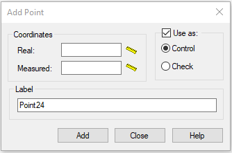
2. Enter the real point coordinates in the Real field;
3. Enter the pair name in the Label field, otherwise this pair will be named PointNN by default;
4. Enter the measured points coordinates in the Measured field or specify them on the screen using  button. If this is not done, their coordinates will coincide with the real ones and can be changed later;
5. If necessary, in the Use as field, change the type of pair from Control to Check or, by clearing the checkbox, define the pair type as Unused;
6. Press ENTER or select Add to create the pair and continue the operation.
Specifying measured points on the screen
The measured points can be specified on the screen using the mouse:
1. Select the calibration pair to be changed from the list of the Calibration dialogue box or on the screen. The program will highlight the selected point with help of “grips”;
2. Specify the selected pair using  button or by the Zoom to command of the context menu. The program pans the image so that to show the measured point of the selected pair in the center of the screen;
Info: NanoCAD is a simple, low cost, and yet powerful, CAD app for personal computer, that delivers an outstanding user experience by providing enhanced performance, full capability, a classic interface and native.dwg format support. nanoCAD has been built to deliver design and project documentation for all engineering purposes. nanoCAD includes a full suite of basic and advanced CAD tools for 2D/3D design and creating industry-standard DWG-compatible CAD files. Our tool supports groundbreaking, collaborative and customizable features to enhance your efficiency, and includes a few API’s, allowing anything from routine task automation to complex CAD app development. You may download nanoCad for free, using the links below, and purchase later, in case you like it.
Post your comment on this topic.