
3D-Component Features
The tab is used to configure 3D settings 3D. The tab is available with a license for 3D.
- Common settings
- 2D views
- Pseudo section properties
Common settings
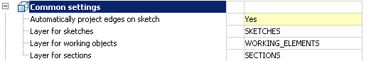
Automatically project edges on sketch
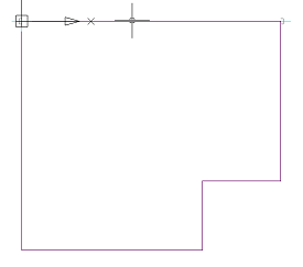
The parameter when adding a new sketch adjusts the display of the projection of the edges of a flat face taken as the working plane for the sketch.
Call command “Add planar sketch”.
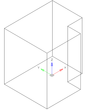
Specify a flat face as a work plane.
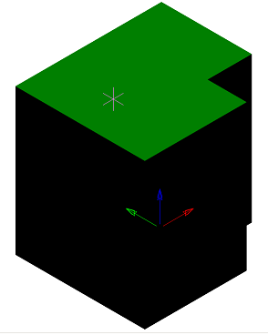
Depending on the setting, a projection will be added to the sketch.
 Yes No
Layer for sketches
It allows you to customize the name of the layer on which will be placed flat sketches.
Layer for working objects
It allows you to customize the name of the layer on which the objects will be located.
Layer for sections
It allows you to customize the name of the layer on which section will be located.
2D views
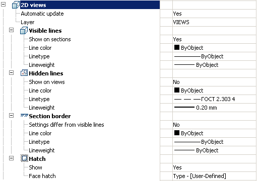
Automatic update
Sets the update mode 2D views
Layer
It defines the layer which will be located 2D views
Visible lines
Show on sections
Adjusts the image visible lines on sections
Line color
Specifies the color of visible lines
Linetype
Specify the type of visible lines
Lineweight
It determines the weight of visible lines
Hidden lines
Show on sections
It adjusts the display of invisible lines on 2D views
Line color
Specifies the color of hidden lines
Linetype
Specify the type of hidden lines
Lineweight
It determines the weight of invisible lines
Section border
Settings differ from visible
It determines whether the parameters are different boundary lines of the section visible lines
If not, the next line settings are not valid.
Line color
Specifies the color of the boundary line section
Linetype
Specifies the type of the boundary line section
Lineweight
It determines the weight of the boundary line section
Hatch
Show
It controls the display of hatching
Face hatch
Settings such as shading
3D. Pseudo section properties
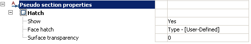
Hatch
Show
It controls the display of hatching.
Face hatch
Settings such as shading.
Surface transparency
Settings such as shading. Default 0 – full transparency.
3D History
 Main menu: 3D –
  3D History…
Ribbon: 3D Tools – Modeling – 3D History.
Functional panel: 3D History.
 Command line: SHOWTAB3DHISTORYNET.
Command line: TABS – select “3D History”.
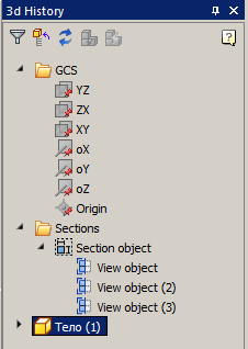
When working in the 3D-design environment, a functional panel containing the model building tree is displayed on the screen.
Building tree – sequence of objects (actions) that make up the model.
Interface
The build tree contains a set of tools:
 Filter Items – massively hides all working objects: planes, axes, points.
 Update tree – updates the tree.
 Collapse parts – Collapses all expanded branches in the tree.
 Update model with regen(3drebuild) – rebuild model.
 Update model(mchist3dupdate) – update model.
Objects of a tree
 – root folder “GCS” (General Coordinate System).
The following objects are bound to it:
 – planes YZ, ZX, XY. By default, they are hidden and have a gray icon
The following shortcut menu commands are available:
- Hide – hides the mapping of the plane in model space.
- Show – shows the mapping of the plane in model space.
- ShowInDocument – focuses the plane in the center of the model space. The command is available when the plane is displayed.
- Create 2d-sketch – call command “Add planar sketch”. Sketch drawing plane is not necessary.
![]() – axis oX, oY, oZ. By default, they are hidden and have a gray icon
– axis oX, oY, oZ. By default, they are hidden and have a gray icon ![]()
 – axis oX, oY, oZ. By default, they are hidden and have a gray icon
The following shortcut menu commands are available:
- Hide – the command hides the display of the axis in model space.
- Show – the command displays the axis in model space.
- ShowInDocument – the team focuses the axis in the center of the model space. The command is available when the axis is displayed.
![]() – origin. Default is hidden and has a gray icon
– origin. Default is hidden and has a gray icon ![]()
 – origin. Default is hidden and has a gray icon
The following shortcut menu commands are available:
- Hide – the command hides the display of the origin in the model space.
- Show – the command shows the display of the origin in the model space.
- ShowInDocument – the team focuses the origin in the center of the model space. The command is available when the origin is displayed.
![]() – root folder “Sections”.
– root folder “Sections”.
 – root folder “Sections”.
The following objects are bound to it:
 – Section. Has child objects
  View, taken from section.
 Planar sketch. When applied to it, 3D Operations is bound to an operation (becomes its child element) and the icon becomes inactive. An exception – assembly sketch.
 Part. It is a 3D object.
The following objects can be attached to the part:
![]() “Planar sketch”.
“Planar sketch”.![]() “Work plane”. Can be located in the root of the tree and enter the structure of objects
“Work plane”. Can be located in the root of the tree and enter the structure of objects ![]() “Part”.
“Part”.![]() “Work axis”. Can be located in the root of the tree and enter the structure of objects
“Work axis”. Can be located in the root of the tree and enter the structure of objects ![]() “Part”.
“Part”.![]() “Work point”. Can be located in the root of the tree and enter the structure of objects
“Work point”. Can be located in the root of the tree and enter the structure of objects ![]() “Part”.
“Part”.![]() “McExtrudeFeature”. 3D operation.
“McExtrudeFeature”. 3D operation.![]() “McRevolveFeature”. 3D operation.
“McRevolveFeature”. 3D operation.![]() “McSweepFeature”. 3D operation.
“McSweepFeature”. 3D operation.![]() “McLoftFeature”. 3D operation.
“McLoftFeature”. 3D operation.![]() “Union”. Contains the union parts.
“Union”. Contains the union parts.![]() “Intersect”. Contains the intersect parts.
“Intersect”. Contains the intersect parts.![]() “Subtract”. Contains the substract parts.
“Subtract”. Contains the substract parts.![]() “McChamferFeature”.
“McChamferFeature”.![]() “McFilletFeature”.
“McFilletFeature”.![]() “McMirrowFeature”.
“McMirrowFeature”.![]() “McRectangularPatternFeature”.
“McRectangularPatternFeature”.![]() “McCircularPatternFeature”.
“McCircularPatternFeature”.
 “Planar sketch”.
 “Work plane”. Can be located in the root of the tree and enter the structure of objects
  “Work axis”. Can be located in the root of the tree and enter the structure of objects
  “Work point”. Can be located in the root of the tree and enter the structure of objects
  “McExtrudeFeature”. 3D operation.
 “McRevolveFeature”. 3D operation.
 “McSweepFeature”. 3D operation.
 “McLoftFeature”. 3D operation.
 “Union”. Contains the union parts.
 “Intersect”. Contains the intersect parts.
 “Subtract”. Contains the substract parts.
 “McChamferFeature”.
 “McFilletFeature”.
 “McMirrowFeature”.
 “McRectangularPatternFeature”.
 “McCircularPatternFeature”.
The following shortcut menu commands are available for the object “Part”:
- Edit – calls for editing the first 3D numbering of the body. To the right of the icon appears the editing symbol
![]() .
. - End edit – completes the previously started editing.
- Rename (F2) – allows you to rename the part.
- Delete (Del) – removes the part and child objects from the tree and model space.
- Hide – hides the part and child objects from the model space.
- Show – shows the part and child objects in the model space.
- Fix – fixes the part in space. You can not move (3D Move), rotate (3D Rotate) or align (3D Align). The part acquires an icon with an anchor
![]()
- Unfix – de-fixes the part. You can move (3D Move), rotate (3D Rotate) or align (3D Align). The parts tied to GCS are fixed by default and can not be de-fixed. Such parts have an icon
![]()
- Suppress – removes the part and child objects from the model space.
- Unsuppress – restores part in model space.
- ShowInDocument – focus
 .
.

Post your comment on this topic.