
Binarization
 Ribbon: Raster– Processing>
  Binarization
Menu: Raster – Processing the raster > Binarization…
 Command line: BINARIZATION
 This functionality is available only in the Raster module.
When performing binarization, a new monochrome image of the specified color is created and placed on the specified layer. Using a certain criterion, the program determines the pixels of the original image (color or grayscale), which should become black (image pixels) and white (background), and then generates a monochrome image and places it on a new raster layer. The criterion for dividing pixels into two sets is determined by the selected binarization method and its parameters (threshold values or a set of color range). Pixels are placed on the image, they are selected in accordance with the setting specified in the tabs of the Binarization dialog box. The new monochrome image is named Original Image Name_N, where N is an integer.
This operation can be applied to multiple images at the same time. If no image is selected, the command will be applied to all visible images located on unlocked layers.
Binarization works on images that have a display border. Using this property, you can limit the binarization area on any image by setting the display border for it.
Binarization methods
To convert color and grayscale images to monochrome, various conversion algorithms are used, called binarization methods. It is recommended to select the conversion method appropriate for the type of image.
Brightness threshold
The Brightness threshold method converts color pixels with brightness values above the specified level to background points, and below that level to image points.
This method can be used to convert both color and grayscale images. When converting a grayscale image, the program uses the grayscale of this image. When converting a color image, the grayscale is determined by the brightness value of colored points.
Threshold by RGB
When using the Threshold in RGB method, specify three separate thresholds for the Red, Green and Blue components. The program converts colored points with Red, Green and Blue values below the corresponding thresholds to black points (image points) of a monochrome image.
Brightness ranges
The Brightness ranges method converts colored pixels with any brightness value to image points. This method selects a number of base gray levels. These levels are used as the midpoints of the ranges. For each selected level, you can define the half-lengths of the ranges. The half-length of the range is the number of gray levels below and above the selected level.
Brightness ranges method converts pixels whose gray level is within the specified ranges to image points. The rest of the pixels are converted to background points.
This method can also be used to convert color and grayscale images. The gray level calculation for colored points is described in the Brightness Threshold section.
Ranges by RGB
Using this method, you can convert color pixels belonging to specified RGB ranges to image points.
To set the RGB range, first select the center color of the range. Red, Green and Blue components of this color determine the position of the center point of the RGB range. For each color component (R, G and B), specify the corresponding half-lengths of the ranges. The red, green, or blue range half-length is the number of R, G, or B levels below and above the selected R, G, or B level. For example, if the R level for the selected color is 50 and the range half length is 10, then the RGB range contains colors with an R component from 40 to 60.
Ranges by HSV
The Range by HSV method simplifies the conversion of RGB color images. It converts pixels of similar colors to image points. Colors that are similar from the point of view of human perception are called analogous (red – orange, dark green – light green, etc.).
To convert an image using the Range by HSV method, specify one or more HSV ranges. The HSV range is determined by the selected color and the half-lengths of the H, S, V ranges. The HSV range is similar in structure to the RGB range. Hue is expressed as an angle from 0° to 360°, and Saturation and Value – as a percentage from 0 to 100.
When converting grayscale images, the results of applying this method are of poor quality.
Configuring binarization
To fine-tune the binarization procedure, you need to choose the appropriate method. The type of the selected method determines the tuning method. For each of the two threshold methods, you should assign one or three threshold values in the histogram. For any range method, you should specify a set of ranges of appropriate types that contain the colors to be extracted.
In addition, for any method, it is necessary to assign a layer on which the image obtained as a result of binarization will be placed.
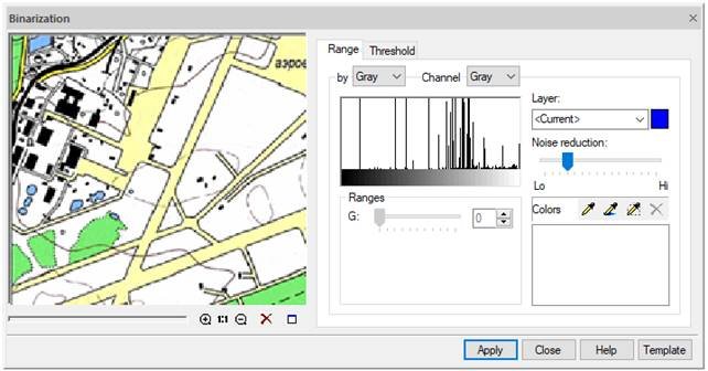
The Binarization dialogue box.
Until options are specified, the preview shows the original view of the image. But as soon as the selection of parameters begins, the results of binarization settings will be dynamically displayed in this window.
Setting range binarization
In the Binarization dialogue box, select the Range tab.
In the By list, select the desired type of the range method.
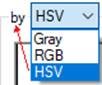
The adjustable parameters depend on the selected method.
Specify a set of ranges that capture the colors of those color image data (objects) that should be transferred to a separate monochrome layer.
Adding a range
Click
 or
or  button and specify in the image a pixel of the color of the data to be binarized .
 Or click
  button and specify the area. An elements corresponding to the created range will appear in the Colors list. By successively clicking the buttons and indicating similar colors, achieve an acceptable result in the preview window.
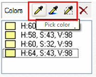
When configured, the preview window dynamically displays the results of adding each range. The most reliable results are obtained by viewing the image at a scale of 1:1.
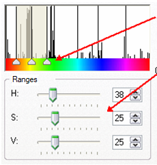
Changing parameters of the created range
If adding a range causes unwanted capture of image pixels, you can change its parameters using the channel histogram sliders or sliders and input fields in the Ranges section
Deleting a range
If you cannot achieve acceptable results by adjusting the range or it is selected by mistake, select it in the Colors list and click Remove color.
Use the Noise reduction slider to improve the binarization quality.
To binarize large “filled” areas, increase the value of this parameter (closer to Low mark) to reduce the amount of raster “garbage” and unfilled holes in the objects obtained during binarization.
To obtain a monochrome image of small or thin objects (texts, symbols, level lines or grids), decrease the value of this parameter to prevent distortion of the shape of small objects.
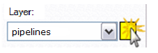
Set the color and name of the layer on which the binarization result will be placed:
- enter the name in the Layer field;
- specify the layer’s color by clicking on its swatch. Select Color in the windows that appears. Click OK.
![]()
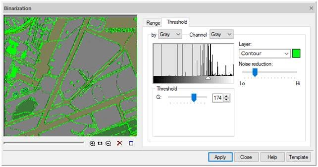
Configuring threshold binarization
In the Binarization dialogue box, select the Threshold tab.
In the By list, select the required method
Find threshold values for the selected method.
![]()
With the selected Threshold by brightness method, select Gray in the Channels list to see the gray level histogram. Specify the threshold value using the slider or G slider.
With the selected Threshold byRGB method, configure the threshold methods R, G and B. For this you can also use sliders on histograms of Red, Green and Blue channels.
Use the Noise reduction slider to improve the binarization quality.
Specify the color and name of the layer on which the binarization result will be placed.
Enter the name in the Layer field. To set the color, click on its swatch and make a selection in the window that appears. Click OK.
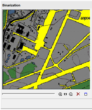
The binarization procedure is started by the Apply button.
![]()
![]()
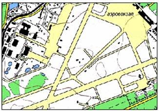
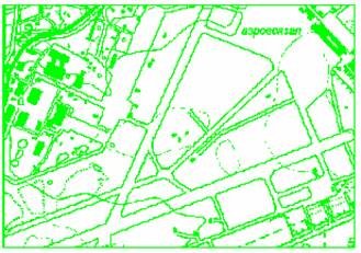
The binarization result is a monochrome image of data having black and close to it pixel colors on the original color raster.
Info: NanoCAD is an easy-to-use, cheap, and yet powerful, CAD platform for Windows, that delivers an outstanding user experience by providing high performance, full capability, a classic interface and native.dwg format support. nanoCAD has been built to deliver design and project documentation for all engineering purposes. nanoCAD includes a full suite of basic and advanced CAD tools for 2D/3D drawing and creating industry-standard DWG-compatible CAD files. Our freeware ensures progressive, collaborative and customizable features to improve your efficiency, and includes a few API’s, allowing anything from routine task automation to complex CAD application development. You may download nanoCad for free, using the links below, and purchase later, in case you like it.
Post your comment on this topic.