
Chamfer
 Ribbon: Home, Draw – Modify >
  Chamfer
Menu: Modify – Chamfer …
Toolbar: Modify –
 Command line: CHA, CHAMFER
This command is used to create chamfers at the points of intersection of objects, with automatic dimensioning ability. The command allows the creation of several chamfers individually.
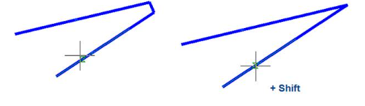
The Chamfer command can be used for quick trimming or lengthening of selected objects. To do so, press the SHIFT button when you select objects: a current value of chamfer radius is temporarily changed to 0 and objects are lengthened or trimmed to intersection point.
After launching the command, the dialog box for specifying the chamfer parameters opens:
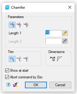
Parameters:
 |
This button switches on the mode for creating a chamfer with similar lengths. In this mode the Length 2 parameter is unavailable. 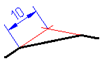 |
|---|---|
 |
This button switches on the mode for creating a chamfer with different lengths. 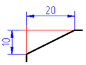 |
 |
This button switches on the mode for creating a chamfer by length and angle. In this mode there is a Corner parameter instead of the Length 2 parameter.  |
| Length 1 | The first length of the chamfer. This field is used also to specify chamfers with similar lengths. |
| Length 2 | The second length of the chamfer. |
| Angle | Angle of the chamfer. |
 |
This button temporarily closes the dialog box to permit measuring the chamfer length and angle on the drawing. The Value picker dialog box appears to perform measurements. |
 |
This button switches on the mode for cutting of full contour lines. 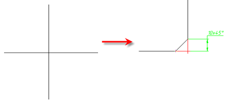 |
 |
This button switches on the mode for cutting of partial contour lines before their intersection. 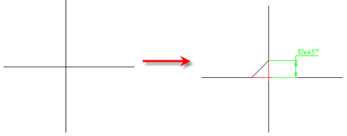 |
 |
This button switches on the mode without lines cutting. 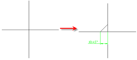 |
 |
This button temporarily closes the dialog box to permit copying of properties from created chamfers. |
 |
This button switches the automatic dimensioning mode on/off. 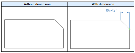 |
 |
Build auxiliary lines – the switch that controls the display of an auxiliary line when dimensioning the chamfer. 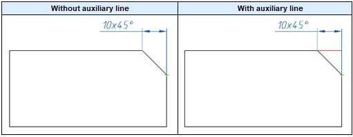 |
| Show at start | When this check box is clear, Chamfer dialog box is not displayed, i.е. it allows you to reconfigure the command to work in a non-dialogue mode. For a repeated call of the dialogue, select the prOperties option in the command line or in the context menu. Such mode of operation is convenient, when you have to frequently use the command without changing its parameters. |
 |
This drop list sets Object scale for dimension object. Field with a drop-down list that sets the drafting scale for a dimensional object created as a result of the command. This field is displayed only in case when the Measurement scale mode is selected in the program status bar. 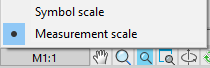 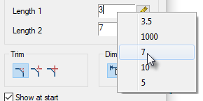 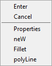 |
Command options:
| Properties | The Chamfer dialog box opens to change the chamfer parameters. |
|---|---|
| neW | Finishes the creation of one group of chamfers and starts another. The command is applied when you need to create some chamfers with similar dimensions on one object and with the same dimensions on another object: 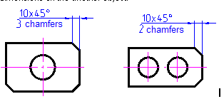 |
| Fillet | Switches to the mode for creating fillets. The Fillet dialog box opens to specify the parameters for the fillet. |
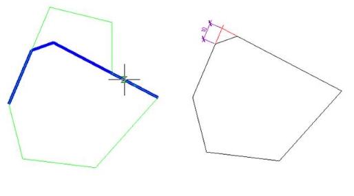
| polyLine | Switches to the mode of making chamfers along a whole selected polyline. Only segments with lengths which are more than chamfer length are processed. It is recommended to specify the same values for both chamfer lengths. This option is available for symmetrical chamfer. Auto dimensions and cutting of countor modes are ignored. 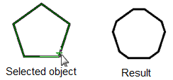 |
Features of the command operation
The command works in 3D. to perform the command, the original primitives should lie in the same plane. If you press and hold the SHIFT key while selecting the second object, then a corner will be formed (snapping at the intersection point and cutting off).
When making an insertion, a polyline retains its integrity. If as a result of the command, one polyline is formed of two polylines, then it will be a single polyline object.
If you select segments of one polyline separated by other segments, then all these intermediate segments are deleted.
Chamfer command, non-dialogue option
Command line: CHA, CHAMFER
Building chamfers using the command line.
Specify first line or [?/Undo/POlyline/Distance/ANgle/Trim/mEthod/Multiple]:
Command options:
| ? | Opens additional options for selecting objects. |
|---|---|
| Undo | Undoes the previous action in the command. |
| POlyline | Creates chamfers for all polyline vertices that are intersection points of two straight line segments. When the Trim > Trim mode option is set, the chamfer lines become new polyline segments. |
| Distance | Specifies the chamfer length from the intersection point of the first and the second objects. If both values are zero, then the selected objects or line segments are lengthened or trimmed to the intersection point. You can specify the length in the drawing or by entering a value in the command line. |
| ANgle, Trim, mEthod, Multiple | Specifies the chamfer length |
Command prompt:
| Select objects or [?]: | Select an object. |
|---|---|
| Select objects or [?]: | Select the next object or press ENTER to stop the command. |
Info: NanoCAD is a simple, inexpensive, and yet powerful, CAD application for Windows, that allows an outstanding user experience by providing high performance, full capability, a classic interface and native.dwg format support. nanoCAD has been built to deliver design and project documentation for all engineering purposes. nanoCAD includes a full suite of basic and advanced CAD tools for 2D/3D drafting and creating industry-standard DWG-compatible CAD files. Our tool supports progressive, collaborative and customizable features to improve your efficiency, and includes a few API’s, allowing anything from routine task automation to complex CAD software development. You may download nanoCad for free, using the links below, and buy later, if you like it.
Post your comment on this topic.