
 Ribbon: Topoplan – Modify TIN >
  Boundary Mesh
Menu: Ground – Editing TIN >  Boundary Mesh
Toolbar: Editing TIN > Boundary Mesh
 Command line: NG_MESH_BOUNDARY
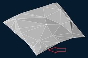
The command purpose is to remove faces with edges of a certain length, which can prevent from the correct construction of contours.
Preliminary actions
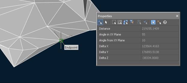
Before running the command it is necessary to define the length of edges. Measurement can be performed by the Distance between points (DIST) command. To do this, run the command with the enabled ENDpoint snap and make measurement. In this case, the obtained distance values will be displayed in the Properties toolbar:
Mesh Boundary
The command options are set on the Properties bar.
Options:
| _.Only external boundary | Yes – changes will only affect the outer triangles. When you specify No, triangles inside a mesh can be changed. |
|---|---|
| Maximum edge length | It is necessary to specify a value slightly less than that measured by the Distance between points (DIST) command. |
| Edge units | Length units – specifies that the value in the Maximum length field is set in the drawing units (meters). Percent – specifies that the value in the Maximum length field is set as percentage. |
| Project points to UCS XY plane | To define what triangles should be removed, lengths of edge projections are compared with the Maximum length. If specify No, projections to the plane of the current view will be used. If specify Yes, lengths of projections to UCS XY plane will be compared. |
Command prompts:
Apply changes [Yes/No/Save/SaveDefault] :
- Yes – mesh boundaring will be performed with the current settings.
- No – if settings have been changed, they are not saved. Boundaring will be performed with the settings that were displayed immediately after running the command.
Edge that prevents from the correct construction of contours  Result of the mesh boundaring

Info: NanoCAD is a user friendly, cheap, and yet powerful, CAD application for personal computer, that delivers an outstanding user experience by providing high performance, full capability, a classic interface and native.dwg format support. nanoCAD has been built to deliver design and project documentation for all engineering purposes. nanoCAD includes a full suite of basic and advanced CAD tools for 2D/3D design and creating industry-standard DWG-compatible CAD files. Our tool supports innovative, collaborative and customizable features to raise your efficiency, and includes a number of API’s, allowing anything from routine task automation to complex CAD software development. You may try nanoCad for free, using the links below, and buy later, in case you like it.
Post your comment on this topic.