
Import from GIS
 Ribbon: Topoplan – Import/Export >
  Import from GIS
Menu: Ground – Import/Export >  Import from GIS
Toolbar: Import/Export > Import from GIS
 Command line: GEOIMPORT
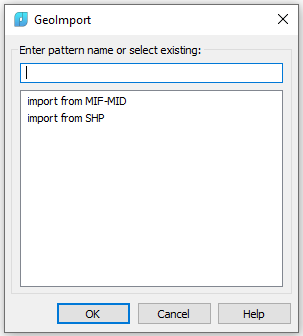
The command imports polylines and point objects from *.SHP and *.MIF files.
After running the command, it opens the dialogue box in which you need to select an existing import template from the list or to create a new one.
Each import template can contain one or more nested object class templates.
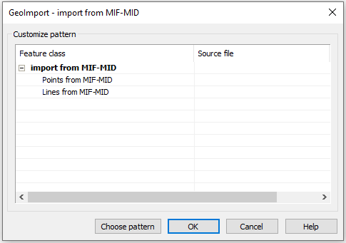
First, create a new object class template, and then specify the corresponding output file. Template names are displayed in the left column of the dialogue (Feature class), and output files – in the right one (Source file).
To create a class template, expand the class collection, click the empty field of the last stream in the left column and enter the name of a new template:
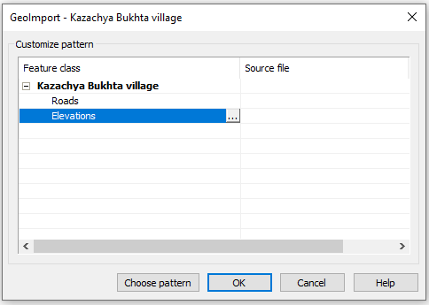
NOTE: A name should not contain the following characters: \ / : * ? “ ” < > |
The context menu is available:
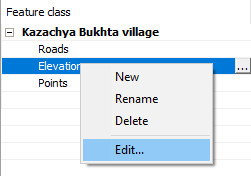
Click
 button to the right of a template name to edit it or select Edit in the context menu
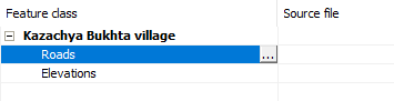
A class template is a set of rules for data conversion. It determines which objects will be imported and sets the correspondence between the parameters of the external format objects and nanoCAD objects.
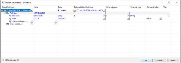
Table columns can be hidden using the context menu called by the right click.
Sequence of configuring a template:
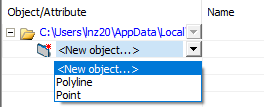
1. In the Object/Attribute column, select a type of objects to be imported from an external file.
Only one type of objects should be specified in the template – if two or more are specified, they will not be taken into account.
It specifies the type of objects that should be imported into the drawing from a file:
- Polyline – export of linear objects from the external file with converting them to a polyline object.
- Point – export of point objects from the external file.
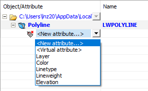
2. If you need to import all objects of this type, and do not need to specify additional import conditions, then click OK to close the dialogue box. Otherwise, click on the “+” sign to the left of the added object type, and specify the parameters to which the import condition will be applied.
3. If the value of this parameter should not inherit the value of the imported object parameter, but should simply receive a previously known value (for example, Roads layer existing in the document or color red), then in the Constant value column you should select the required value from the drop-down list.
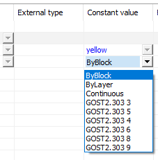
This list presents the standard values and values contained in the current nanoCAD document. To set a non-standard value, assign it to the object of the current document, then you can select it in the drop-down list.
4. If the parameter value should inherit the parameter value of the imported object, then click in the first cell of the External object/attribute column and select the Scan file in the menu that opens
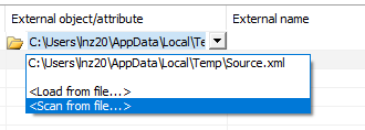
In the dialogue box that opens, specify the file with mif (shp) extension, from which the data should be imported.
As a result, information about all types of imported objects and their parameters will be taken from the specified file.
If you have a ready-made type template in the.xml format, then instead of scanning geo-file, you can select Load from file and specify xml.
5. In the External object/attribute column, select from the drop-down list the external parameter, the value of which should be inherited by the internal parameter in the Object/Attribute column.
6. You can use filters to restrict the import of objects by certain values of their parameters. Thus, you can import objects only with a certain parameter value or a range of values, objects with empty/non-empty parameter value. For import operations, restrictions are imposed on the parameters of external objects from the External object/attribute column.
To set a filter, double-click a cell in the Filter column. This will open a window, the content of which depends on the type of value of the external object parameter (in the External value column.
A type of dialogue for numeric values (Integer, Real, etc.):
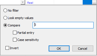
Look empty values – only objects with a missing parameter value (selected in the External object/attribute column) will be imported.
Compare – enter a value to which the comparison operator from the Task Drop-down list will be applied
Task – a logical operator. Together with the Compare field value, sets the filtering condition (the screenshot shows the condition=3).
Invert – a logical operator that inverts a given condition. It can be used only in case of Search for empty values. In other cases, it is ignored.
Info: NanoCAD is a simple, cheap, and yet professional, CAD program for personal computer, that allows a great user experience by providing enhanced performance, full capability, a classic interface and native.dwg format support. nanoCAD has been built to deliver design and project documentation for all engineering purposes. nanoCAD includes a full suite of basic and advanced CAD tools for 2D/3D design and creating industry-standard DWG-compatible CAD files. Our software ensures groundbreaking, collaborative and customizable features to enhance your efficiency, and includes several API’s, allowing anything from routine task automation to complex CAD software development. You may try nanoCad for free, using the links below, and purchase later, if you like it.
Post your comment on this topic.