
Creation of custom properties windows
Creation of Custom Properties Fields
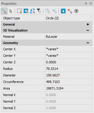
The fields in the Properties panel display information about selected objects which can be dragged onto an existing or created toolbar, creating a custom properties field:

CAD drafting Creation of Custom Properties Windows 0
After dragging, only the right column with the values from the Properties panel is shown in the toolbar. Name of the property (left column is not displayed).
The value of a property is shown in the custom properties field after selection of the object, which property is shown in the field. The field remains empty if an object is not selected or if the selected object does not have properties contained in the field. If several objects are selected, the field is empty unless similar objects are selected, for example circles of one diameter.
One user properties fieldcan contain several fields from the Properties panel.
If the user window contains several properties of one properties group or several properties of one object type, only one property (the top property in the Properties Setup) is shown when the object is selected:
In this case, when a circle is selected the radius value will be shown; if a line is selected, its length value will be shown; if a single line text is selected, its height will be shown.
The 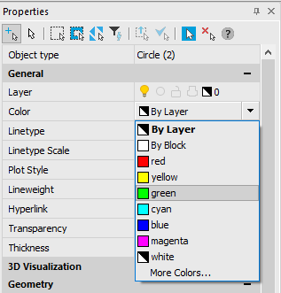 and
and  buttons are used to move the selected property in the list.
To display the Geometry.Diameter property when a circle is selected, use the to move this property above the Geometry.Radius property:
The 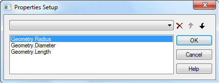 button deletes the selected property from the list.
To display two or more properties from one group or one object type, create several fields on the toolbar.
As an example, we will show how to create a toolbar with 3 custom properties fields, the first displays the circle diameter and text height, the second – circumference and text rotation and the third – circle area and text oblique.
To create custom properties’ fields:
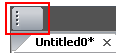
1. Create a new toolbar (for more information how to create a new toolbar see in the Toolbars tab section (Tuning nanoCAD – Tuning the interface)):

2. Select a circle.
3. Place the cursor over the Diameter field in the Properties panel.
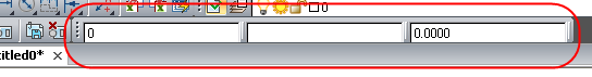
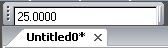
4. Drag the Diameter field, using the left mouse button and ALT button, onto the created toolbar:

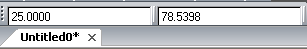
5. Drag the Circumference field to the right of the first field on the toolbar in the same way:

6. Drag the Area field to the right of the second field on the toolbar:
CAD software Creation of Custom Properties Windows 10
7. Press ESC to deselect the circle.
8. From the context menu of the first field select Setup:
9. In the drop-down list of the dialog box that appears, select the Text.Text height property:
10. Select OK to close the dialog.
11. From the context menu of the second field select Text.Rotation.
12. Select OK to close the dialog.
13. For the third field select the Text.Obliquing.
14. Select OK to close the dialog.
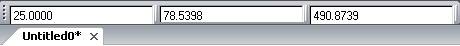
15. After selecting any circle on the drawing, the values for its diameter, circumference and area are shown:
16. After selecting any single line text on the drawing, the values of its height, rotation and oblique are shown:
To delete a field from a new toolbar:
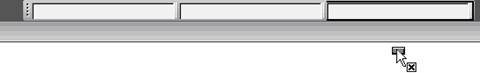
1. Place the cursor over the field:

2. When the field is selected, press ALT and drag the field into the drawing area:
NOTE: The Disable All switches off the display of properties’ values not only in the user fields, but in the fields of Properties and Styles standard toolbars.
Post your comment on this topic.