
Create View Frames
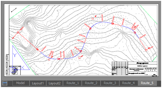
The possibility to split a drawing into prepared sheets for subsequent printing has been implemented. The Create frames command allows you to place view frames of future layouts on the drawing. The Create Layouts by Frames command creates layouts based on frames with the desired design and scale.
Creating Frames
 Ribbon: Topoplan –Design of Layouts >
 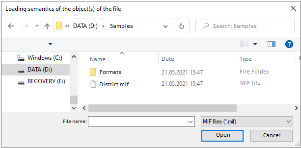 Create frames
Menu: Topoplan – Design of Layouts >  Create frames
 Command line: CreateViewFrame
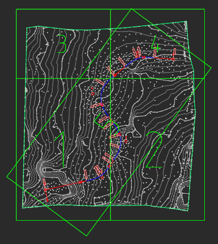
The command allows you to create frames in the model space for the subsequent formation of designed layouts. Each frame is a viewport of such a layout.
Each frame carries information about the template, format and scale of the layout. The design of the future layout will be taken from the template in accordance with the format.
After the Create frames command starts, you can configure the options of future layout for the frame:
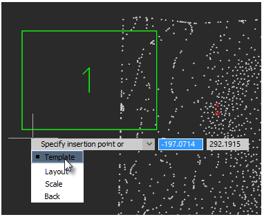
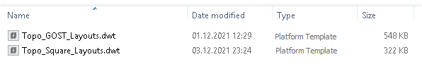
Template – a template file containing a list of available formats with frame design. You can specify a template for formats according to standards or for a topographic tablet.
After selecting a template, specify the layout size for the inserted frame.
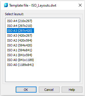
Layout – the option allows you to assign a layout format without reassigning the template.
Scale – selection of the topographic scale. By default, the scale of the created sheet is set according to the current TOPOSCALE.
The frame profile corresponds to the bounds of the layout’s viewport that will be created from them with the Create Layouts by Frames command. In case of selecting horizontal layout formats, this is clearly visible.
A visible cutout is a place for a stamp, which in small horizontal formats can occupy a significant part of the layout. 
After setting all the parameters, specify the position of the view frame in the drawing. In this case, you can use the nanoCAD precise positioning tools to snap to axial, auxiliary lines, mesh, points, or existing view frames. You can rotate frames and use other standard mechanisms for placing objects in the drawing workspace.
When inserting a frame, you can change its anchor point. By default, the anchor point is located in the lower left corner of the frame. Changing the anchor point of the frame is convenient in case of designing routes, as they can go in any direction. This is also true for tablets, where numbering usually goes from left to right and from top to bottom. But, when trying to insert the second row, it is already inconvenient to use the anchor point in the bottom left.
For cycle change of the anchor point, just press the Space key or select the Anchor point keyword. The anchor point can be set to any vertex of the frame. 
Post your comment on this topic.