
Array
This command is used to create two-dimensional arrays of the selected objects by placing their copies on the specified circle (polar array) or in the nodes of the specified rectangular grid (rectangular array).
The Array – Associative command parameter allows you to specify whether arrays will be associative or non-associative.
Elements of an associative array are stored in a single object – an array. In an associative array you can change the number of elements and the distance between them. Such properties of an associative array as the number of elements and distance between them can be changed using the array grips or on the properties toolbar.
After exiting the command non-associative arrays split into independent objects.
The commands to create arrays are located:
 Ribbon: Home, Draw – Modify
Menu: MOdify – Array
Toolbar: Modify
 Command line
 |
 |
 |
- Select the cmomand to create the array.
- Select objects to create the array, press Enter.
A preview of a defualt array will be displayed on the screen. - Specify the array parameters.
Data are entered from the command line:
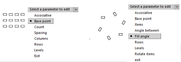
Select a parameter to edit [Associative/Base point/Count/Spacing/COlumn/Rows/Levels/Exit]:
Or with a context entry:
![]()
- Click Exit to complete the command.
Command line: AR, ARRAYCLASSIC
Array command opens the Array dialog box.
There is the  Select objects command in the top corner of the dialog box; it temporarily closes the dialog box whilst selecting the source objects. There is a line showing the number of selected objects – Objects selected below the button.
There is a preview window below the line.
Rectangular array
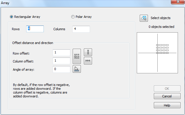
Parameters:
| Rectangular array | Switches on the rectangular array mode. |
|---|---|
| Rows: | Number of rows. |
| Columns: | Number of columns. |
Offset distance and direction
| Row offset: | Distance between rows. |
|---|---|
| Column offset: | Distance between columns. |
| Angle of array: | Field to enter an angle of array. |
| Buttons: | Button temporarily closes the dialog box to specify the distance or an angle on the screen. |
 |
Specify the distance between rows on the screen. |
 |
Specify the distance between columns on the screen. |
 |
Specify the distance between rows and columns on the screen. |
 |
Specify an angle of array on the screen. |
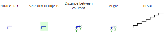
Example of creating stairs using rectangular array:
- Create one more stair;
- Select created objects;
- Specify number of rows – 1;
- Specify number of columns – 7;
- Specify distance between columns (specify point 1, after that point 2);
- Specify angle (specify point 1, after that point 2);
Polar array
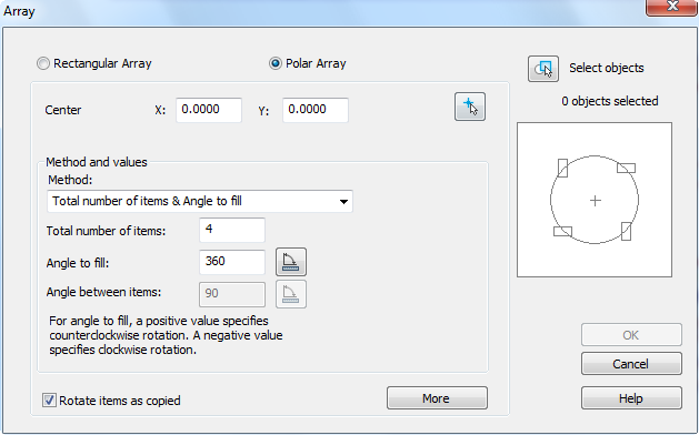
The More button opens an additional section of the dialog box to specify the base point of the X,Y axes.
Parameters:
| Polar array | Switches on the polar array mode. |
|---|---|
| Center point: X: Y: | Fields to enter the X, Y coordinates of the array center. |
 |
Button temporarily closes the dialog box to specify the center of the array on the screen. |
Method and values
| Method: | A drop-down list to select the method of array creation. Available options in the drop-down list:
|
|---|---|
| Total number of items: | Number of elements (with source object). |
| Angle to fill: | Angle of array fill. |
 |
Button temporarily closes the dialog box to specify the fill angle on the screen. |
| Angle to fill: | Angle of array fill. |
| |
Button temporarily closes the dialog box to specify the angle between neighboring array items. |
| Rotate items as copied | Switches on/off the mode for rotating the elements in the array. |
| More/Less | This button opens/closes an additional part of the dialog box. |
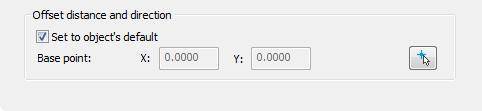
Offset distance and direction
| Set to object’s default | Switches on/off the mode for specifying the base point. |
|---|---|
| Base point: X: Y: | Fields to enter the X,Y coordinates of the base point. |
| |
Button temporarily closes the dialog box to specify the base point on the screen. |
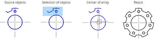
Example of creating polar array:
Info: NanoCAD is an easy-to-use, low cost, and yet powerful, CAD program for Windows, that provides an outstanding user experience by providing enhanced performance, full capability, a classic interface and native.dwg format support. nanoCAD has been built to deliver design and project documentation for all industrial purposes. nanoCAD includes a full suite of basic and advanced CAD tools for 2D/3D drafting and creating industry-standard DWG-compatible CAD files. Our program supports innovative, collaborative and customizable features to improve your efficiency, and includes a number of API’s, allowing anything from routine task automation to complex CAD software development. You may download nanoCad for free, using the links below, and buy later, in case you like it.
Post your comment on this topic.