
Bounding Prism
 Ribbon: View – Viewport Tools >
  Bounding Prism
Menu: View >  Bounding Prism
Toolbar: View toolbar > Bounding Prism
 Command line: MCLIP
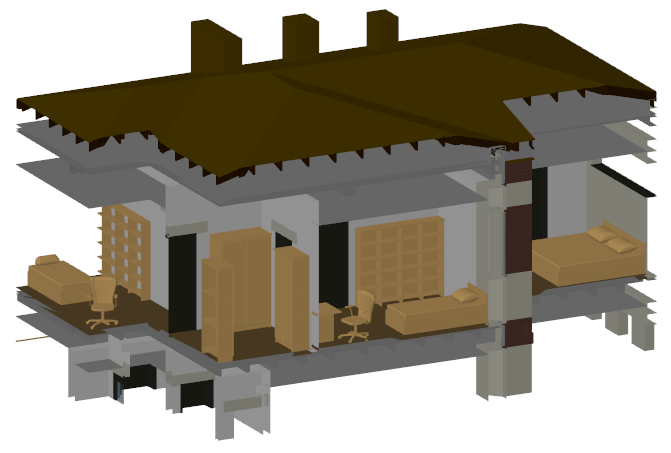
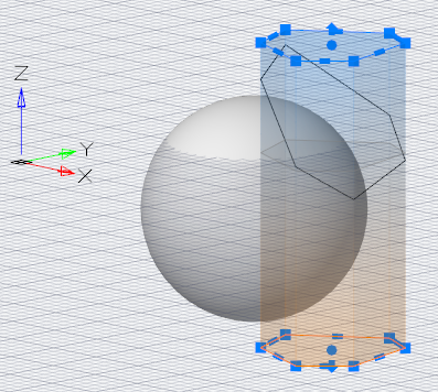
For each model space viewport, you can create a bounding prism – an area in a three-dimensional space, beyond which all the graphics are not displayed.
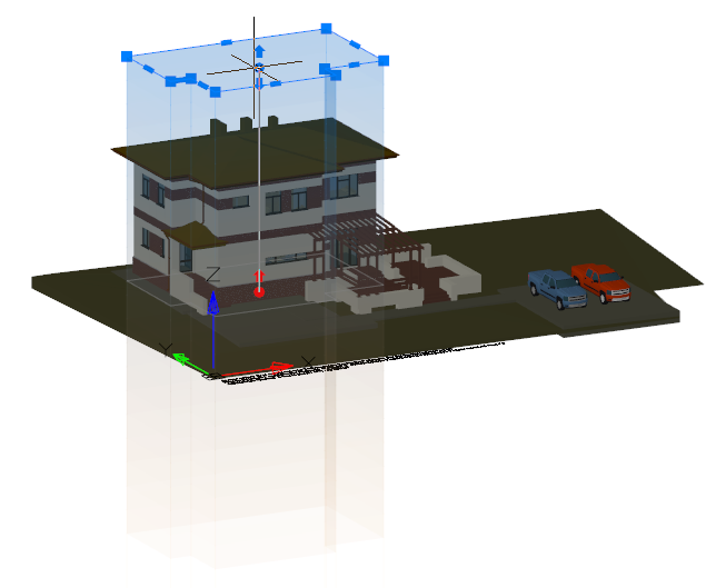


The area is defined as a rectangular or polygonal prism with grips. The prism can be:
- created by specifying a contour on the screen,
- created on the basis of an existing polyline,
- based on a bounding box of selected objects.
The prism above the XY plane of the UCS is blue, below it is orange. The grey outline of the prism is displayed in the XY plane.
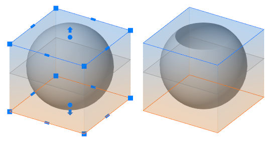
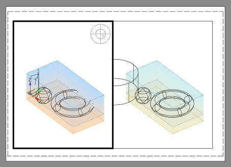
Drag grips to place the upper and the lower prism cutoff planes. Otherwise the upper and lower displaying area will be unlimited.
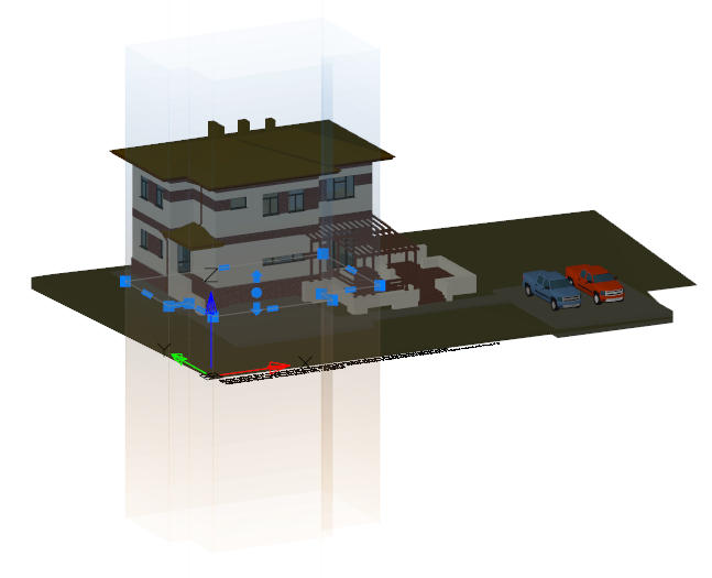

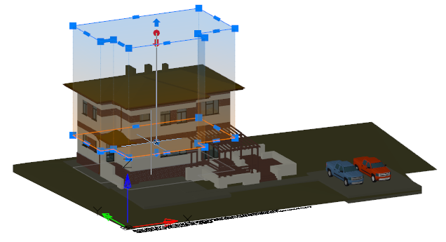
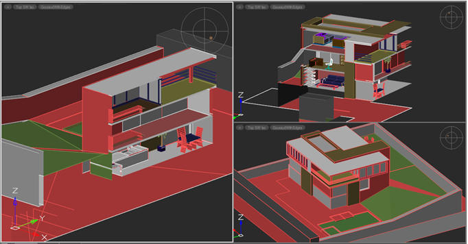
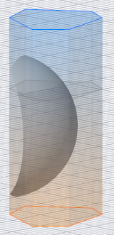
A prism is created taking into account the direction of the UCS axes. The following is an example of constructing a prism based on the same polyline, but in different UCSs.


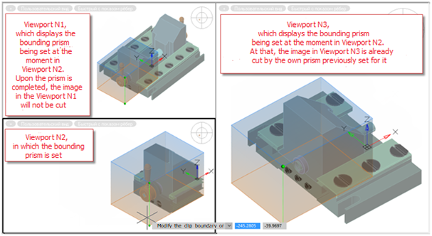
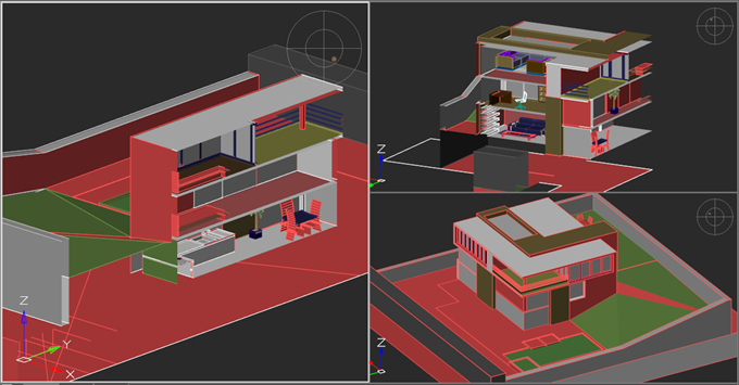
A bounding prism is created for each viewport. It will not restrict the image in other viewports.
At the time of creating or editing a prism, it is displayed in all viewports, but its effect only applies to the screen in which it was created or was selected for editing. When you finish adjusting the prism, it will crop the image only in the viewport for which it was created
To create a new or edit an existing prism, go to the desired viewport and run the Bounding prism command.
While editing a prism, you can switch to another viewport to continue editing it from a more comfortable angle. At the same time, editing of the prism that belongs to the previous viewport (in which the Bounding Prism Bounding prism command was run) will continue in the new viewport, and not the current one. A prism in its own viewport is displayed more vividly than in the others so that it is always clear which viewport it belongs to, regardless of which viewport is currently active.
For each model space viewport, its own bounding prism should be created.
An existing prism can be changed, deleted or disabled/enabled. If the prism is disabled, graphics outside the prism become visible. Disabled prism object is still present in the model space and can be switched on later.
When saving a document, the prism is also saved.
Options:
| _.New | Create a new bounding prism for the current view of the model space. |
|---|---|
| Delete | Delete the existing bounding prism in the current view of the model space. |
| Modify | Change the existing bounding prism in the current view of the model space. Grips appear on the prism that allow you to change its geometry. |
| Enable | Activate the effect of an existing prism on the current view of the model space. Enabled by default. |
| Disable | Inactivate the effect of an existing prism on the current view of the model space. Prism is preserved, but does not limit the space of the view. |
| Exit | Exit command. |
Command prompts when choose the New option:
| _.polyLine | Select an existing closed polyline that will define the contour of the prism. Then, using grips, set the upper and lower prism cutoff boundary, if necessary. The prism will be built in the direction of the UCS axes of the current view. |
|---|---|
| Selection | Select the objects around which a rectangular prism will be built. Then, using grips, change the upper and lower prism cutoff boundary, if necessary. |
| Rectangular | Draw a rectangular contour that will define the contour of the prism. Then, using grips, set the upper and lower prism cutoff boundary, if necessary. |
| Polygonal | Draw a polygonal contour that will define the contour of the prism. Then, using grips, set the upper and lower prism cutoff boundary, if necessary. |
| _ eXit | Finish the process of creating a new prism. |
Info: NanoCAD is a user friendly, cheap, and yet professional, CAD freeware tool for Windows, that provides a great user experience by providing top-level performance, full capability, a classic interface and native.dwg format support. nanoCAD has been built to deliver design and project documentation for all engineering purposes. nanoCAD includes a full suite of basic and advanced CAD tools for 2D/3D drawing and creating industry-standard DWG-compatible CAD files. Our tool supports progressive, collaborative and customizable features to improve your efficiency, and includes a few API’s, allowing anything from routine task automation to complex CAD software development. You may try nanoCad for free, using the links below, and purchase later, in case you like it.
Post your comment on this topic.