
Named UCS
 Ribbon: View – Coordinates >
  Named UCS…
Menu: Tools – Named UCS…
Toolbar: UCS –
 Command line: UCSMAN, UC
The command opens the UCS dialog box, where you can select from the specified UCS, the parameters and UCS icon modes for viewports.
The UCS dialog box can be opened from the Properties panel:
Named UCS tab
This tab contains the list of coordinate systems specified in the current drawing.
If the UCS is not saved or named, it is shown as Unnamed in the list.
The current UCS is marked with  sign.
sign.
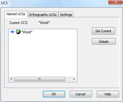
To set a UCS as current:
1. Select the UCS from the list.
2. Select the Set Current button.
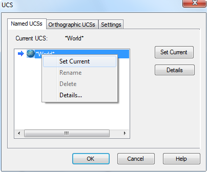
You can set the UCS as current by double clicking on the UCS name or select Set Current from the context menu:
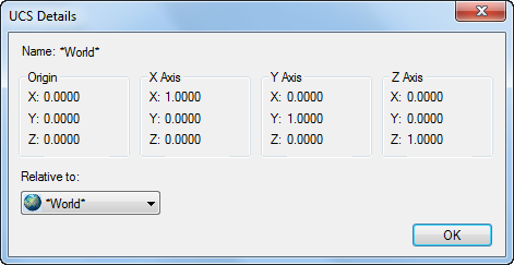
The Details button (or command from the context menu) opens the UCS Details dialog box with information about the coordinates of the selected UCS:
To delete a UCS:
1. Select the UCS from the list,
2. Open the context menu,
3. Select Delete.
To rename a UCS:
1. Select the UCS from the list,
2. Open the context menu,
3. Select Rename,
4. Enter the new name.
Orthographic UCS tab
This tab contains six orthogonal coordinate systems which can be set for a UCS selected in the Relative to drop-down list. All named UCS existing in the current drawing are shown in the Relative to drop-down list.
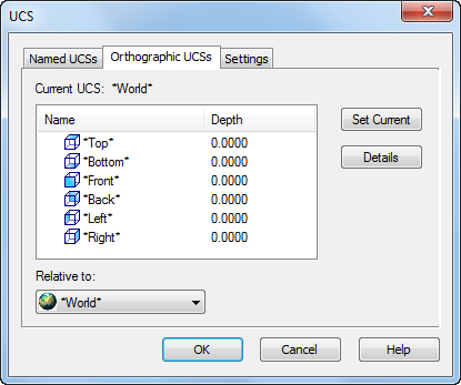
To set an orthogonal UCS:
1. Select the UCS from the list,
2. Select the Set Current button.
You can set an orthogonal UCS by double clicking on the UCS name or select Set Current from the context menu:
Options of the context menu:
| Set Current | Sets the orthogonal UCS as current one. |
|---|---|
| Reset | Restores the origin of the selected orthogonal coordinate system (the origin has (0,0,0) coordinates of the base coordinate system). |
| Depth | Sets the direction between the XY plane of the orthogonal UCS and the parallel plane, set through the origin of the base coordinate system. The parallel plane can coincide with XY, YZ or XZ planes of the base coordinate system. |
| Details | Opens the UCS Details dialog box with information about the coordinates of the selected orthogonal UCS. |
To set an orthogonal UCS:
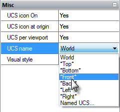
1. Click in the UCS name field on the Properties panel.
2. Open the drop-down list and select appropriate orthogonal UCS:
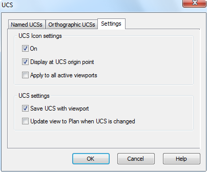
Settings tab
The tab is used to show and change the UCS icon modes and the UCS modes saved with the viewport:
Parameters:
UCS icon setting
| On | Displays the UCS icon in the current viewport. |
|---|---|
| Display at UCS origin point | Displays the UCS icon in the current viewport at the origin. If the UCS origin is outside the viewport and the parameter is switched off, the UCS icon is specified in the left corner of the viewport. |
| Apply for all active viewports | Applies the UCS icon modes to all the active viewports of the current drawing. |
UCS settings
| Save UCS with viewport | Saves the UCS mode with the viewport. If the parameter is switched off, the UCS of the current viewport is used for the specified viewport. |
|---|---|
| Update view to Plan when UCS is changed | Restores the view in plan when the coordinate system is changed in the current viewport. |
Info: NanoCAD is an easy-to-use, affordable, and yet professional, CAD application for personal computer, that delivers an outstanding user experience by providing enhanced performance, full capability, a classic interface and native.dwg format support. nanoCAD has been built to deliver design and project documentation for all engineering purposes. nanoCAD includes a full suite of basic and advanced CAD tools for 2D/3D drafting and creating industry-standard DWG-compatible CAD files. Our tool ensures creative, collaborative and customizable features to boost your efficiency, and includes several API’s, allowing anything from routine task automation to complex CAD application development. You may download nanoCad for free, using the links below, and buy later, if you like it.
Post your comment on this topic.