
Model space and paper space
There are two distinct working environments, or spaces, in which you can create objects in a drawing. In nanoCAD they are represented by the Model and Layout tabs.
Typically, a model composed of geometric objects is created in a three-dimensional space called model space. A final layout with specific views and annotations of this model is created in a two-dimensional space called paper space. These spaces are accessible on two or more tabs near the bottom of the drawing area: the Model tab and one or more Layout tabs.
Layout tabs access an area called paper space. In paper space, you place your title block, create layout viewports to display views, dimension your drawing, and add notes.
You can create a single layout viewport that fits the entire layout or create multiple layout viewports in the layout. Once you create the viewports, you can change their size, their properties, and also scale and move them as needed.
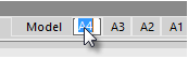
It is possible to create multiple layouts in a drawing. Each layout can contain different plot settings and paper sizes. The layout tabs are located in the bottom part of the document window, next to the Model tab. To switch between the Model tab and Layouts, click the necessary tab:
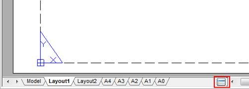
To quick switch between the model space and layouts, use the
 button located at the end of tabs line. This button also allows you to switch between the named views available in the document. Left click to open a context menu that displays all the tabs and named views available in the document:
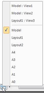
The top part of the menu displays the named views; the bottom part displays the Model and layouts tabs. The current space is marked with
 To switch between tabs or named views, it is necessary to click on the corresponding name in the menu. When you switch to a named view, there is auto-panning of the view on the screen.
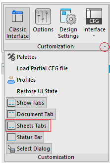
The display of layout tabs is enabled/disabled by  Sheets Tabs command located in the View menu and on the ribbon (Manage tab – Customization group).
You can rename, delete and add layout tabs unlike the Model tab. The last (the only one in the document) layout tab cannot be deleted.
Another important difference between model space and paper space is that you create non-overlapping viewports in the model space, i.e. snap-together at the boundaries. In model space you can print only the current viewport. Viewports in the paper space are floating. They can be moved to any part of the layout. Their boundaries can be close to each other and overlapped or be located at some distance from each other. You can print all the viewports located on the layout at the same time.
To work with a layout, use the command from the Insert menu – Layout item, or from the Layout toolbar, from the Layouts Manager dialog box, or from the context menu that opens by right clicking the Model tab or a Layout tab.
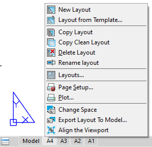
To create a new layout, use the Add Layout command. To delete a layout, use the Delete Layout command.
You can rename the current layout by double-click on its tab or by selecting the Rename layout command from the tab’s context menu:
To rename any layout in a document, use a separate LAYOUT command.
The format of the displayed layout is set in the Page Setup dialog box.
You can rename, delete and add layout tabs unlike the Model tab.
Another important difference between model space and paper space is that you create non-overlapping viewports in the model space, i.e. snap-together at the boundaries. In model space you can print only the current viewport. Viewports in the paper space are floating. They can be moved to any part of the layout. Their boundaries can be close to each other and overlapped or be located at some distance from each other. You can print all the viewports located on the layout at the same time.
To work with a layout, use the command from the Insert menu – Layout item, or from the Layout toolbar, from the Layouts Manager dialog box, or from the context menu that opens by right clicking the Model tab or a Layout tab.
To create a new layout, use the Add Layout command. To delete a layout, use the Delete Layout command. To rename a layout, use the Rename Layout command.
The format of the displayed layout is set in the Page Setup dialog box.
NOTE: The print area of the layout for the current format settings and printer is displayed by a dashed line.
You can change the layout color in the Options dialog box using the Color settings item – Layout Paper.
When you prepare a layout, you typically go through the following process:
1. Create a model of your subject on the Model tab.
2. Click a Layout tab and specify layout page settings, such as plotting device, paper size, plot area, plot scale and drawing orientation.
3. Insert a title block into the layout.
4. Create a new layer to be used for the layout viewports.
5. Create the layout viewports and position them on the layout.
6. Set the orientation, scale and layer visibility of the view in each layout viewport.
7. Add dimensions and annotate in the layout as necessary.
8. Turn off the layer containing the layout viewports.
9. Execute the plot setting of the layout.
10. Plot the layout.
Post your comment on this topic.