
View cutting planes
 Ribbon: View– Navigate >
  SecantPlanes
Ribbon: Point clouds– Navigate > SecantPlanes
 Command line: DVIEW
For a view you can set front and/or back clipping planes that hide all objects located outside the space between these planes. The position of clipping planes is regulated by sliders moving them closer of farther from the point of view.
NOTE: View clipping planes are not drawing objects, but are display parameters (conditions).
Command options:
| _.Front | Displays a slider at the top of the workspace that allows you to adjust the position of the front clipping plane. The back clipping plane is not specified (i.e., it is assumed to be at an infinite distance from the point of view). |
|---|---|
| Back | Displays a slider at the top of the workspace that allows you to adjust the position of the back clipping plane. The front clipping plane is not specified (i.e., it is assumed to be the same as the screen plane). |
| BOth | Displays a slider at the top of the workspace that allows you to adjust the position of both the front and back clipping planes. |
| Off | The option is available when the command has already been called earlier and the clipping planes have been set. Hides a slider at the top of the workspace and turns off clipping planes. |
Command prompts:
| Select clipping plane or [Front/Back/BOth/Off]: | Specify the required option. |
|---|
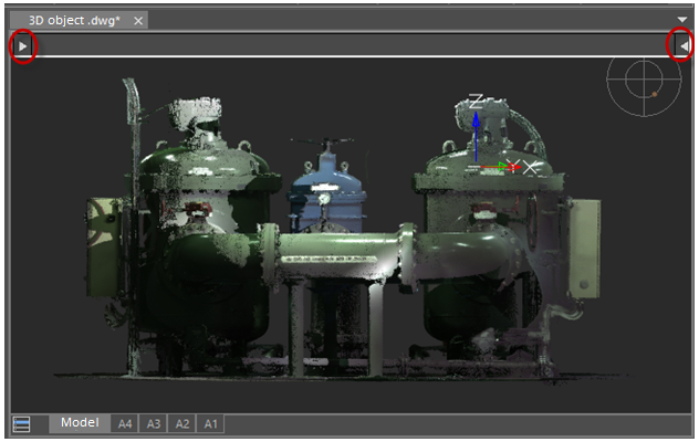
After starting the command and selecting the desired mode for specifying the clipping planes, you should adjust the position of these planes by moving the slider grips in the upper part of the workspace. Initially, the front plane is located at the point of view, and the back one at the maximum distance.
Display mode for both clipping planes. The position of planes is not adjusted:
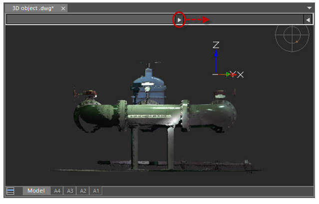
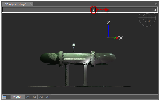
Moving the front clipping plane away from the viewpoint while clipping the front objects:
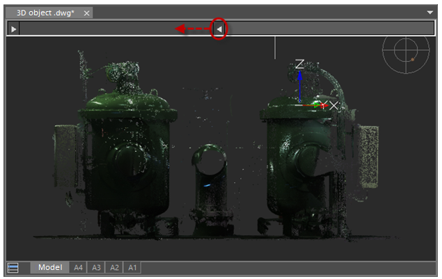
Moving the back clipping plane towards the point of view while clipping off the background objects:
Info: NanoCAD is a user friendly, cheap, and yet professional, CAD program for Windows, that allows a great user experience by providing top-level performance, full capability, a classic interface and native.dwg format support. nanoCAD has been built to deliver design and project documentation for all engineering purposes. nanoCAD includes a full suite of basic and advanced CAD tools for 2D/3D drawing and creating industry-standard DWG-compatible CAD files. Our software ensures groundbreaking, collaborative and customizable features to enhance your efficiency, and includes a number of API’s, allowing anything from routine task automation to complex CAD app development. You may try nanoCad for free, using the links below, and purchase later, if you like it.
Post your comment on this topic.