
Horizontal, vertical and aligned dimensioning
In the following examples, horizontal, vertical and aligned dimensions are created by using the Auto command.
 Ribbon: Home, Annotate – Dimensions >
  Linear
Menu: Dimensions –  Auto
Auto
Toolbar: Utilities –
 Command line: D, DIMLINEAR, DIM, DLI
To dimension you can use also the Horizontal, Vertical and Aligned dimension commands.
Menu: Dimensions –  Horizontal
Toolbar: Utilities –
Command line: DIMHOR
Menu: Dimensions –  Vertical
Toolbar: Utilities –
Command line: DIMVER
Menu: Dimensions –  Aligned dimension
Toolbar: Utilities –
Command line: DAL, DIMALIGNED
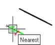
To specify the horizontal dimension of the line:
- Start the Auto command.
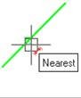
- Place the cursor over the line to show its dynamic highlighting and display the character . Left click to confirm the dimensioning:
![]()
- Move the cursor down to change the character to :
![]()
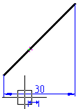
- Left click to set the position of the dimension line:
![]()
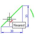
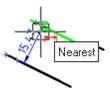
To specify the vertical dimension of the line:
- Place the cursor over the line to show its dynamic highlighting and display the character . Left click to confirm the dimensioning:
![]()
- Move the cursor to the right to change the character to :
![]()
- Left click to set the position of the dimension line:
![]()


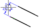
To specify the aligned dimension of the line:
- Place the cursor over the line to show its dynamic highlighting and display the character . Left click to confirm the dimensioning:
![]()
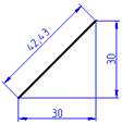
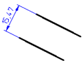
- Move the cursor to the left to change the character to :
![]()
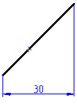
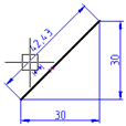
- Left click to set the position of the dimension line:
![]()
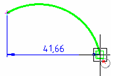
For dimensioning the arc length using characteristic points:
- Start the Auto command.
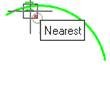
- Place the cursor over the arc to show its dynamic highlighting:
![]()
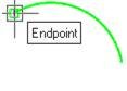
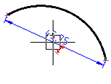
- Move the cursor near to the endpoint of the arc. When the snap marker appears, left click to choose the endpoint of the first extension line of the dimension:
![]()
- Move the cursor to the other endpoint of the arc and left click to choose the endpoint of the second extension line of the dimension:
![]()
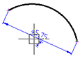
- Move the cursor to the middle of the arc to display the character :
![]()
- Move the cursor down and to the left to change the character to :
![]()
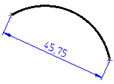
- Left click to set the position of the dimension line:
![]()
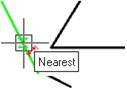
For dimensioning between two parallel line segments:
- Start the Auto command.
- Select the lower line segment by highlighting it and left click:
![]()
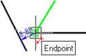
- Select the top line segment by highlighting it and left click when the horizontal character appears:
![]()
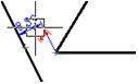
- Move the cursor up and to the left to change the character to :
![]()
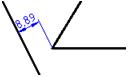
- Left click to set the position of the dimension line:
![]()
To draw the dimension from a point to a line segment:
- Start the Auto command.
- Select the lower line segment by highlighting it and left click:
![]()
- Select the endpoint of the second line segment using the snap:
![]()
- Move the cursor up and to the left:
![]()
- Left click to set the position of the dimension line:
![]()
Info: NanoCAD is a user friendly, cheap, and yet powerful, CAD software tool for Windows, that allows an outstanding user experience by providing high performance, full capability, a classic interface and native.dwg format support. nanoCAD has been built to deliver design and project documentation for all engineering purposes. nanoCAD includes a full suite of basic and advanced CAD tools for 2D/3D drawing and creating industry-standard DWG-compatible CAD files. Our program supports innovative, collaborative and customizable features to boost your efficiency, and includes a number of API’s, allowing anything from routine task automation to complex CAD software development. You may try nanoCad for free, using the links below, and purchase later, in case you like it.
Post your comment on this topic.