
Plot Preview
The right part of Page Setup and Plot dialogs is the window for preview of the specified plot setups.
Change of plot setups is dynamically displaed in the preview window.
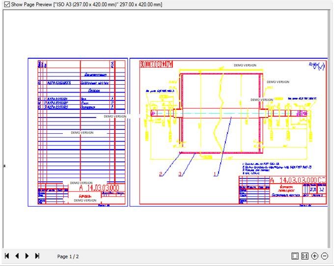
The preview window provides two options for displaying the specified plot area: schematic (simplified) and normal, in which the plot setting is displayed in the view it will be output to the plot device.
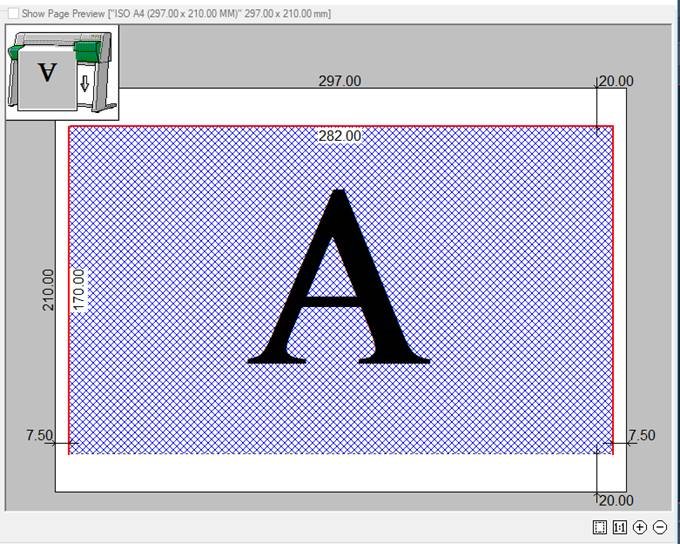
Conventions in schematic (simplified) preview:
Dashed line – the plot area boundaries for the selected plot device and specified paper format.
Numbers – size of the specified paper format and indentations to the plot boundary. Indentations from the paper edge to the plot boundaries depend on the selected plot device.
Blue hatch and letter A – location and orientation of the specified plot area on the page.
Red line – warning that the specified plot area is outside the plot margins.
 The icon with printer image (in schematic symbol in preview window) that displays the positioning of the specified plot area on a paper page. The arrow shows the direction of paper exit at plotting.
ATTENTION! For a layout that does not have an assigned plotter, preview is not available.
Options of the preview dialog box (for normal view):
 |
Zoom all | Button to display the whole specified plot area in the preview window. |
 |
Zoom 1:1 | Button to display the specified plot area at a scale of 1:1. |
 |
Zoom in | Button to zoom in the image in the preview window. |
 |
Zoom out | Button to zoom out the image in the preview window. |
Additional options displayed for a multipage plot:
 |
First page | Button to display the first page of a plot set in the preview window. |
 |
Previous page | Button to display the previous page of a plot set in the preview window. |
 |
Next page | Button to display the next page of a plot set in the preview window. |
 |
Last page | Button to display the last page of a plot set in the preview window. |
 Displays the number of the page viewed in the preview window, and the total number of pages of the plot set.
It is possible to zoom and pan an image in the preview window by a mouse after clicking inside the window:
- to zoom an image – rotate the mouse wheel.
- to pan an image – move the mouse with the left or right button pressed and held, as well as with a mouse wheel.
A separate Plot Preview dialog box with normal view of the plot set can be opened from:
 Ribbon: Output – Plot >
  Preview
Menu: File –  Preview…
Toolbar: Main –
 Hot keys: CTRL+F2
Command line: PREVIEW
In the Batch plot dialog box, the Plot preview is opened by Preview button.
The possibility of quick plot of the content using the Plot button is added to the parameters of the preview window in the Plot Preview dialog box:
 Plot
Plot  The button to plot.
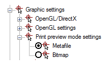
When plotting individual files (with rich graphics, a large number of viewports, etc.) the message “Not enough memory to create preview” can appear in the preview window. In this case it is necessary to change the setting in the Print preview mode settings section (Graphic settings item of the Options dialog box).
By default, the Metafile (WMF) parameter is set:
Modifying and adding the paper formats
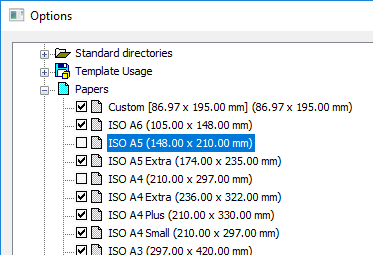
The composition of paper formats list of the Paper size and orientation section in Plot and Page Setup dialog boxes depends on formats specified in the Papers section of Options dialog (the Tools menu– Options). In the same section it is possible to change the existing paper format or create a new one.
To edit the list of paper formats:
1. Enter the Papers section of the Options dialog box.
2. Set the label of formats that should be displayed in the list:
To add a new paper format:
1. Select the Papers section name of the Options dialog box. To create a new paper format based on the existing one, select the required format in the section list.
2. Click the Add button.
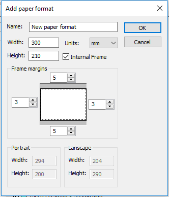
3. In the opened Add paper format dialog box:
- specify the new format name;
- select the measurement units;
- enter the values of format width and height;
- if necessary, set size of the internal frame: set the Internal frame mark and specify the values of margins from the format edge in the Frame margins section:
![]()
NOTE: The plot area sizes are set depending on the specific plot device used, as they are determined by the plot device manufacturer.
NOTE: When setting the paper size, it is necessary to consider the minimum and maximum acceptable sizes for the specific plot device used, which are also determined by the plot device manufacturer.
4. Click OK to close the dialog box.
5. Click OK to close the Options dialog box.
To modify a paper format:
1. Enter the Papers section of the Options dialog box.
2. Select the format to be modified.
3. Click the Modify button.
4. In the opened Modify paper format dialog box, repeat actions of 3-5 items from the previous section. You should not change the format name.
The newly created paper formats are displayed in the Paper size and orientation drop-down list in the Plot and Page Setup dialog boxes after selecting a specific plot device.
ATTENTION! The paper formats for which the specified sizes are more or less than those acceptable for a specific plot device are not displayed in the Paper size and orientation list for this device.
Editing the list of paper formats
The content of the drop-down list for selecting paper formats of the Paper size and orientation section in the Plot and Page Setup dialog boxes can be edited.
The  Filter paper button of the Paper size and orientation section opens the Edit paper list dialog box, in which it is possible to disable the unused formats, enable additional ones or delete paper formats that belong to the custom formats list.
The dialog box contains the list of all available paper formats that can be included in the list.
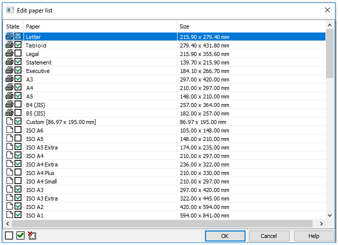
Options:
| _.State |
|
|---|---|
| Paper | Names of standard and custom paper formats. |
| Size | Sizes of standard and custom paper formats. |
 Paper format belongs to the list of formats of the selected plot device.
 Paper format belongs to the list of custom formats nanoCAD.
 Format is deleted from the list.
To edit the list of paper formats:
1. Select the format in the dialog box.
2. Select/clear the checkbox  in the State column or use the dialog buttons:
![]() Turn off paper
Turn off paper![]() Turn on paper
Turn on paper![]() Delete custom paper
Delete custom paper
NOTE: Paper formats that belong to the current plot device and are marked with![]() cannot be deleted.
cannot be deleted.
 Turn off paper
 Turn on paper
 Delete custom paper
To edit the status or delete several formats at once use the multiple selection:
- While holding down SHIFT key, select all formats located between the first and the last left click.
- While holding down CTRL key, it is possible to add any format from the list by left click.
ATTENTION! Editing in the Paper formats list editor dialog box is synchronized with the Papers list of the Options dialog box (the Tools menu – Options). The custom formats are deleted simultaneously from all format lists.
Info: NanoCAD is a simple, low cost, and yet powerful, CAD program for Windows, that provides an outstanding user experience by providing enhanced performance, full capability, a classic interface and native.dwg format support. nanoCAD has been built to deliver design and project documentation for all engineering purposes. nanoCAD includes a full suite of basic and advanced CAD tools for 2D/3D drawing and creating industry-standard DWG-compatible CAD files. Our freeware ensures groundbreaking, collaborative and customizable features to enhance your efficiency, and includes a few API’s, allowing anything from routine task automation to complex CAD application development. You may download nanoCad for free, using the links below, and buy later, if you like it.
Post your comment on this topic.