
Export to GIS
 Ribbon: Topoplan – Import/Export >
  Export to GIS
Menu: Topoplan – Import/Export >  Export to GIS
Toolbar: Import/Export > Export to GIS
 Command line: GEOEXPORT
The command exports polylines and point objects to *.SHP and *.MIF files.
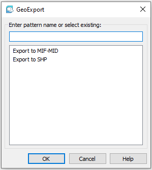
After running the command, select the objects to be exported. In export templates the objects are filtered from the selection specified at this step. After selecting objects, a dialogue for multiple export to geo-formats opens. In the dialogue that opens, select an export template from the list or create a new one.
Creating and editing an export template
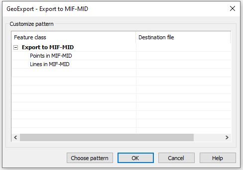
Each export template can contain one or more nested templates of Feature classes (Feature class column), which are associated with the output external files of SHAPE or MID/MIF format, where the data will be exported (Destination file column).
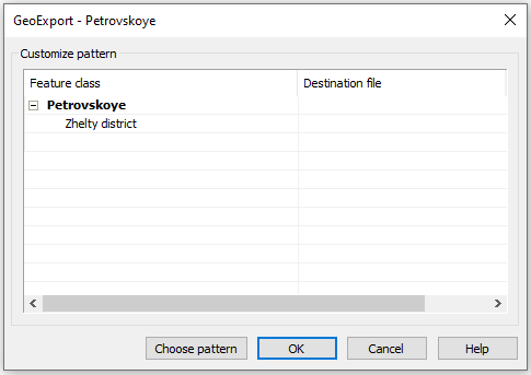
To create a class template, expand the export template and double-click an empty field in the Feature class column. In the text field, enter the name of the new template:
NOTE: The name should not contain the following characters: \ / : * ? “ ” < > |
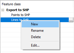
The same can be done using the context menu available in this dialogue:
To edit the content of a class template, select its name in the Feature class column and click button on the right or select Edit in the context menu.
This will open the template settings dialogue. A class template is a set of rules for data conversion. It determines which objects will be exported and sets the correspondence between the parameters of nanoCAD objects and external format objects.
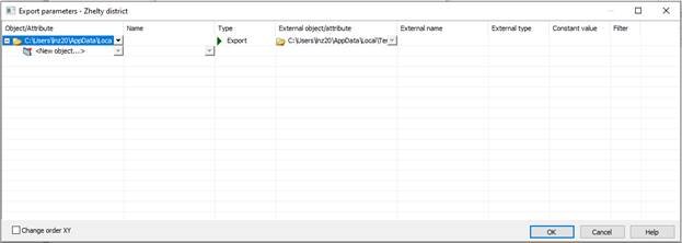
The Change order XY box is checked in the case, when the coordinates along the X axis and coordinates along the Y axis should be changed during export.
First, you should specify the type of objects to be exported: Polyline, 2dPolyline, Point.
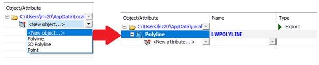
Usually, in the nanoCAD drawing, roads and buildings are represented by polylines:
Only one type of exported objects can be specified in each template. To export other types, create new templates.
NOTE: the objects will be exported not from all objects in the document, but from the selection that was made at the first command prompt, immediately after its start.
Below there is a table for converting types of objects when exporting to MID/MIF format:
| nanoCAD objects type | MID/MIF, SHP objects type |
|---|---|
| Polyline not closed (property Closed = No) |
Polyline |
| Polyline closed (property Closed = Yes) |
Polygon (Region) |
| Point | Point |
Filtering the exported selection of objects using attributes
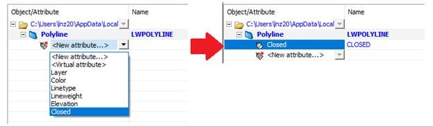
If you need to export not all the objects of the specified type, but a certain selection, then you should specify the attribute value by which the selection is carried out. For example, to export all buildings, as a rule, it is enough to set the Polyline object with the Closed “real” attribute value.
Click the field and select the Closed attribute in the drop-down list
The attribute value is set by clicking
 button in the Filter column.
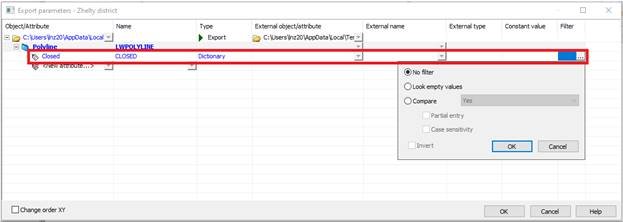
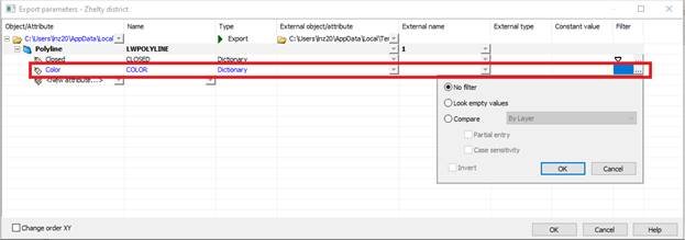
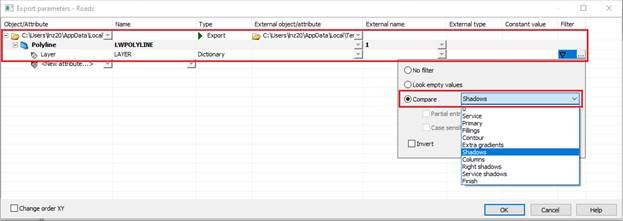
In the dialogue that opens, select Compare, and in the drop-down list select the attribute value – Yes.
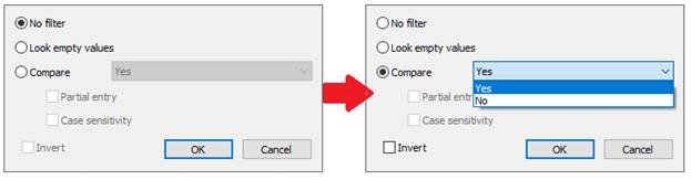
Filtering options:
| _.No filter | Filtering by attribute value is not required. I.e., the attribute is not used to create the required selection of objects (and only for export of values to an external file). When the No filter item is set, the  icon in the Filter field of the Export settings dialogue disappears. icon in the Filter field of the Export settings dialogue disappears. |
|---|---|
| Search for empty values | Objects with an unassigned value of this attribute will be selected. |
| Compare | Allows you to set a specific value for an attribute. A list of fixed values is available for most of the attributes. For the Level attribute you should enter the value yourself. |
| Partial matching | Available for the Level attribute that does not have a fixed list of values. |
| Match case | Available for the Level attribute that does not have a fixed list of values. |
| Invert | Inverts the selection by the given attribute: the selection will include all objects with the attribute value NOT meeting the specified criteria. |
Now in the Filter column opposite to the Closed attribute, the icon will appear, which means that a value for this attribute has been set and is used as a filter during export.
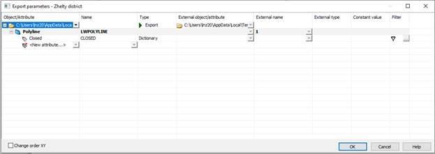
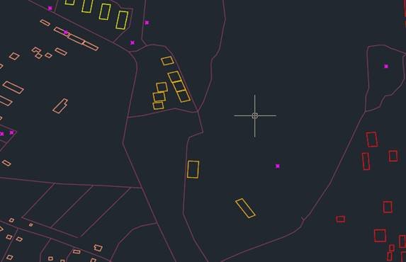
If you use the resulting template for export, then the output file will contain all closed polylines (buildings) of the same color:

To export only yellow buildings with preserving polylines color in the output file, it is required to complicate the template a little.
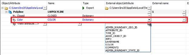
Let’s set one more attribute – Color.
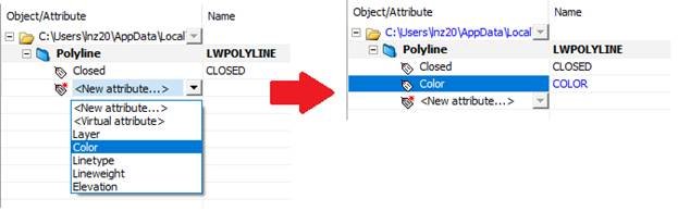
The attribute value should be specified in its filter. To do this, click button in the Filter column next to the corresponding attribute.
In the window that opens, select the desired value. To set the yellow color, select the Compare item and select Yellow from the drop-down list of available values.
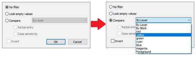
Now all closed yellow polylines will be exported.
Exporting attribute values to the external format
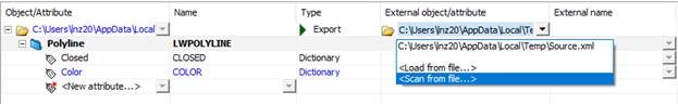
To preserve the color during export, the Color attribute should be matched to the desired external format attribute.
You can get a completed list of external format attributes by loading semantic data from XML file of by scanning an existing MIF or SHP file. To do this, select or in the External object/attribute field from the drop-down list
In the window that appears, specify the file from which you want to get semantic information.
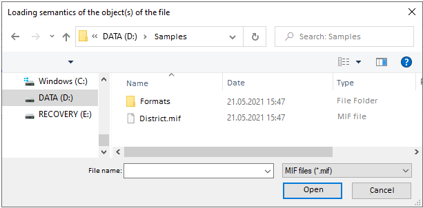
In case of scanning files, a new xml file is created with an identical name containing semantic information,
Now in the External object/attribute column you can specify an external attribute that should inherit the value of the internal Color attribute when exporting objects.
If objects are sorted into layers, it is most convenient to use the Layer attributes to filter objects.
A Virtual attribute is used in a case, when during export for the external files objects you need to set the value of the attribute that is missing in nanoCAD objects.
Geodata objects
After configuring all templates, in the geodata export dialogue, to the right of a name of each template, specify an output file of MIF format, to which the data should be exported.
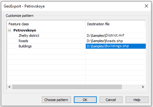
As a result, we created “template-output file” pairs, indicating by what rules and in which file the data should be exported.After creating all “template-output file” pairs, click OK to export the data. The export will be carried out for all templates to which the output file was assigned. Templates without an output file will be ignored.
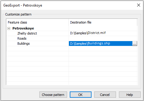
NOTE: In order to avoid data loss, do not indicate the same output file for different templates.
Info: NanoCAD is an easy-to-use, affordable, and yet professional, CAD freeware tool for Windows, that provides a great user experience by providing enhanced performance, full capability, a classic interface and native.dwg format support. nanoCAD has been built to deliver design and project documentation for all industrial purposes. nanoCAD includes a full suite of basic and advanced CAD tools for 2D/3D design and creating industry-standard DWG-compatible CAD files. Our freeware ensures progressive, collaborative and customizable features to improve your efficiency, and includes a few API’s, allowing anything from routine task automation to complex CAD application development. You may try nanoCad for free, using the links below, and buy later, if you like it.
Post your comment on this topic.