
Rectangle by two points
Rectangle
Rectangle is a special case of a closed polyline. The Explode command transforms polyline which rectangle consists of, into segments.
There are three ways to create a rectangle:
· by two points;
· from center (with center in the specified point);
· by three points
 Ribbon: Home, Draw – Draw >
  Rectangle by Two Points
Menu: Draw – Rectangle by >  Two points
Toolbar: Draw –
 Hotkeys: CTRL+ALT+R
Command line: REC,RECT,RECTANG,RECTANGLE
The command allows creating a rectangle from two opposite points.
Parameters of rectangle (length, width, area, rotation angle) can be specified and types of angles (right angle, with chamfer or rounded by radius) can be edited with this command.
Command options available when specifying the center:
cOrner Switches to the mode of drawing a rectangle by two points.
| Chamfer | Sets the chamfer size for the rectangle’s corners.  |
|---|---|
| Elevation | Sets the elevation (Z-axis) for the rectangle. Since the rectangle is a flat figure, the Z-coordinates of its vertices in the UCS are determined by the Elevation parameter  |
| Fillet | Sets the current radius for Fillet of rectangle’s corners.  |
| Thickness | Specifies the 3D height for the rectangle.  |
| Width | Sets the polyline width for building a rectangle.  |
Command options available when specifying other corner point:
|_.Area | Specifying the rectangle area when it is created by area and specified length or by area and specified width.
After setting the area value, the following prompt is displayed in the command line:
Calculate rectangle dimensions based on [Length/Width]:
- Options:
Length – Specifies the rectangle’s lenth.
Width – Specifies the rectangle’s width. |
| Dimension | Height and length of rectangle |
|---|---|
| Rotation | Rotation angle of rectangle by entering its value in the command line or specifying on the screen. The Pick Points option allows specifying a rotation angle by specifying two points on the screen. |
Isorectangle
Creating a rectangle in the current isoplane.
In the command for constructing a rectangle using two points, the Isorectangle option is available only when the isometric mode is enabled: the button in the status bar or the snap type is set to Isometric in the Snap snap setting
Creating a rectangle in the current isoplane.
In the command for creating a rectangle using two points, the Isorectangle option is available only when the isometric mode is enabled: the CAD drafting Rectangle by Two Points 30 button in the status bar or the snap type is set to Isometric in the Snap setting.
1. Enable the isometric mode.
2. Select the command for creating a rectangle by two points.
3. At the prompt of the command line: Specify first corner point or [centeR/Chamfer/Elevation/Fillet/Thickness/Width/Isorectangle]: – select Isorectangle.
Command prompts:
| Specify first corner point or [Dimensions]: | Specify the first corner or select the Dimensions option to create a rectangle by length and width. |
|---|---|
| Specify other corner point: | Specify the second point. |
Isorectangle
Creating a rectangle in the current isoplane.
In the command of creating a rectangle by two point, the Isorectangle option is available only when the isometric mode is enabled:  button in the status bar or the Isometric snap type set in the Grid snap of the drafting settings.
1. Enable the isometry mode.
2. Select the command to create a rectangle by two points.
3. Upon the command line prompt: Specify first corner point or [Chamfer/Elevation/Fillet/Thickness/Width/Isorectangle]: – select Isorectangle.
Ribbon: Home, Draw – Draw >  Rectangle from Center
Menu: Draw – Rectangle by > from Center
Toolbar: Draw –
Command line: RECTCENTER
The command allows creating a rectangle (flat closed rectangular polyline) from two opposite points.
Parameters of rectangle (length, width, area, rotation angle) can be specified and types of angles (right angle, with chamfer or rounded by radius) can be edited with this command.
Command options when a first corner point is specified:
CenteR Switches to the mode of drawing a rectangle from center
| Chamfer | Sets the chamfer size for the rectangle’s corners. |
|---|---|
| Elevation | Sets the elevation (Z-axis) for the rectangle. Since the rectangle is a flat figure, the Z-coordinates of its vertices in the UCS are determined by the Elevation parameter |
| Fillet | Sets the current radius for Fillet of rectangle’s corners. |
| Thickness | Specifies the 3D height for the rectangle. |
| Width | Sets the polyline width for building a rectangle. |
*Command options available when specifying other corner point*%(color-blue)%:
Area Specifying the rectangle area when it is created by area and specified length or by area and specified width. After setting the area value, the following prompt is displayed in the command line: Calculate rectangle dimensions based on [Length/Width]:
Options%%(color-blue):
Length – Specifies the rectangle’s lenth.
Width – Specifies the rectangle’s width.
Dimensions Sets values for creating a rectangle by length and width.
Rotation Specifies the rotation angle of the rectangle by entering its value in the command line or by specifying a point on the screen.
The Pick Point option allows you to set the rotation angle by specifying two points on the screen.

Command prompts:
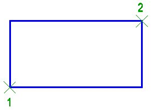
Specify rectangle center or [cOrner/Chamfer/Elevation/Fillet/Thickness/Width]: Specifies the center (point 1).
Specify other corner point or [Area/Dimensions/Rotation]: Specifies the second corner (point 2).
IsorectangleCreating a rectangle in the current isoplane.
In the command for constructing a rectangle using two points, the Isorectangle option is available only when the isometric mode is enabled: the button in the status bar or the snap type is set to Isometric in the Snap snap setting
Creating a rectangle in the current isoplane.
In the command for creating a rectangle using two points, the Isorectangle option is available only when the isometric mode is enabled: the button in the status bar or the snap type is set to Isometric in the Snap setting.
1. Enable the isometric mode.
2. Select the command for creating a rectangle by two points.
3. At the prompt of the command line: Specify first corner point or [centeR/Chamfer/Elevation/Fillet/Thickness/Width/Isorectangle]: – select %
(color-blue)Isorectangle%.
Command prompts
Specify first corner point or [Dimensions]: Specify the first corner or select the Dimensions option to create a rectangle by length and width.
Specify other corner point : Specify the second point.
Info: NanoCAD is a simple, cheap, and yet powerful, CAD application for Windows, that provides a great user experience by providing high performance, full capability, a classic interface and native.dwg format support. nanoCAD has been built to deliver design and project documentation for all industries. nanoCAD includes a full suite of basic and advanced CAD tools for 2D/3D drawing and creating industry-standard DWG-compatible CAD files. Our freeware provides groundbreaking, collaborative and customizable features to enhance your efficiency, and includes a few API’s, allowing anything from routine task automation to complex CAD software development. You may download nanoCad for free, using the links below, and buy later, if you like it.
Post your comment on this topic.