
 Ribbon: Topoplan – Import/Export >
  Import geo-points
Menu: Ground – Import/Export >  Import Geo Points
Toolbar: Import/Export > Import Geo Points
 Command line: NG_IMPORT_POINTS
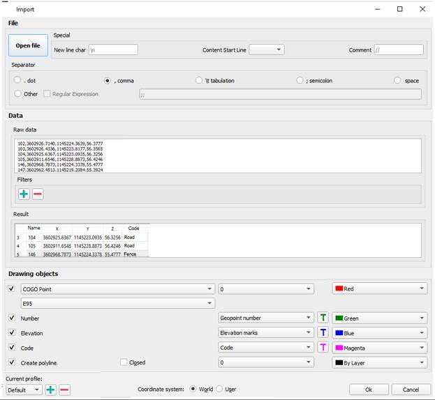
The command is designed to import text files from XYZ and TXT formats. With help of the Survey Files Import Wizard you can configure the rules for uploading file contents.
Options:
| Open file | Open text file CSV, SDR (Sokkia), XYZ and TXT to import geodata. You can open multiple files at the same time. |
|---|---|
| New line character | Allows you to override the newline character. The default character is \n. |
| Content start line | Line number of significant content, if the file beginning contains any service information, except for point coordinates. |
| Comment | Specifies the character that is used to comment lines. Commented lines are not considered as data during import. If there are no comments in the file, then leave the field blank. The default character is \\. |
| Separator | Specifies a character that separates data in a text file. You can choose both predefined ones (period, comma, semicolon, tab character, space), or set any other, if necessary, using regular expressions. |
| Raw data | Preview of text file data. Selected data can be copied. |
| Filters | You can exclude data from import not only manually by deleting cells from the Result table, but also by setting filters. For example, you can exclude from import all points with heights below 52 (column Z) and with a number greater than 350 (column Name). After adding the filter with the CAD software Import Geopoints 10 button, in the drop-down list, select the column by which all imported data will be filtered. Then set the value that the column data should satisfy. The rest of the lines will be excluded from import. Hovering over a filter displays a tooltip with sample values. It is recommended to set filters only after correct data typing in the Result section. |
| Result | The table specifies the correspondence of the text file columns to certain data types: point X, Y and Z coordinates, numbers, point descriptions. The column heading displays the data type. In case of incorrect initial data typing, you can drag one column to another by the header, mutually changing the data in these columns. You can delete selected cells, rows, or columns. Multiple selection is supported using SHIFT and CTRL. Rows or columns are selected by clicking on the heading. Before manually deleting data, it is recommended to filter it out using filters. You can also edit the data after double-clicking on a cell.  |
| Drawing objects | The section determines the form objects the geopoints should be imported from an external file (that is, by what objects they will be represented in the drawing). And also what titles the point label will consist of, and what design they will have. You can import geodata as: · Common Point objects with labels as text objects; · Blocks (like blocks from the Conventional sign bar) · Objects of the Geopoint type with a label. In case of importing data in the form of COGOpoint object, specify a group for them in the drop-down list below.  The list contains only groups of geopoints that exist in the current drawing. To create a new group, select the Create new option and enter a name for the new group. If the Block was selected, the imported points will be presented as block inserts with single-line attributes to display label titles. To do this, a new block will be created in the drawing. The conventional sign for the point marker will be taken from the block in the dropdown list below. 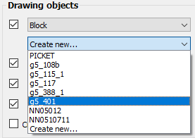 Only the blocks that already exist in the current drawing are available in the list. The blocks will be inserted with a scale that takes into account the values of the current topographic scale. If the Create new option is selected instead of selecting an existing block in the list, then after starting import, the block editor will open to create a point marker (conventional sign) block. The default is a circle. In the block editor, edit the marker, save the block, and exit the editor to complete the import. |
You can mark which attributes will be displayed in the geopoint description on the drawing: geopoint number (name), elevation (Z-coordinate) and code (point description). You can automatically create a polyline connecting all imported points. For example, if these are points of a road or a building.  To place points and titles, you can assign individual layers and colors. Titles can also be assign with a font.   |
|
| Coordinate system | Select in what coordinate system to import geodata: World or Custom ones or recalculate by EPSG codes: |
| Additional Options | The Additional Options button opens the window where you can change the settings for the units (UNITS) with which geopoints should be imported. By default, the current drawing units are used. |
| Current profile | Allows you to save all the settings made in the dialog to a profile for further use. |
Info: NanoCAD is an easy-to-use, affordable, and yet professional, CAD freeware tool for Windows, that allows a great user experience by providing enhanced performance, full capability, a classic interface and native.dwg format support. nanoCAD has been built to deliver design and project documentation for all industries. nanoCAD includes a full suite of basic and advanced CAD tools for 2D/3D design and creating industry-standard DWG-compatible CAD files. Our tool provides groundbreaking, collaborative and customizable features to raise your efficiency, and includes several API’s, allowing anything from routine task automation to complex CAD app development. You may download nanoCad for free, using the links below, and purchase later, in case you like it.
Post your comment on this topic.