nanoCAD Mechanica - A mechanical engineering software

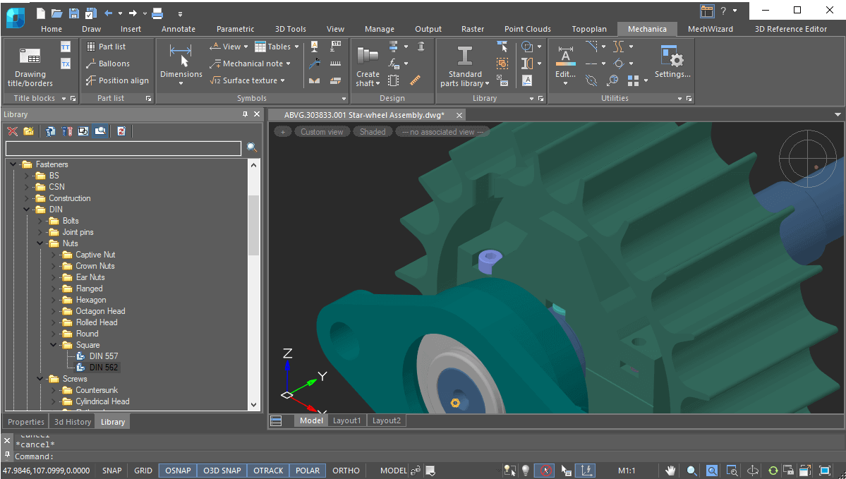
nanoCAD Mechanica is a mechanical engineering tool with 2D drafting and 3D mechanical designing. It is based on an advanced parametric engine, and works with a large library of standard parts. It enables users to carry out fast development of high-quality mechanical engineering drawings and project documentation.

New in Mechanica

  • Assembly Units
  • Changing 3D Type of an Assembly Unit
  • Document Properties Window
  • Assembly Unit Properties Window
  • Specification by 3D Model
  • Specification Positions
  • Stamping
  • Flanging
About nanoCAD Mechanica

Key features

Library of standard and complex parts


  • Search filter
  • Fasteners
  • Standard profiles
  • Reamers
  • Circuit elements symbols
  • Technical sketches
  • Machine accessories
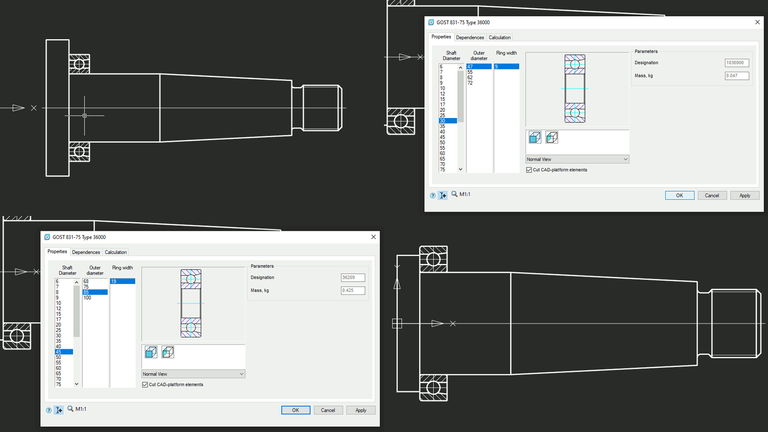
  • Mechanical gears, bearings, shafts, and sockets
  • Electric motors
  • Gear boxes
  • Pipeline fittings
  • Vessels and apparatus
Broad range of design tools

Broad range of design tools


  • Supports multi-sheet drawings
  • Constructs objects and symbols by a variety of methods, such as orthogonal drawing and using object snap
  • Manages drawing order of overlaying objects
  • Draws standard and custom line types, hatches, and fonts with styles
  • Dimensions through multiple methods and places technology symbols
  • Auto selects tolerances and deviations
  • Automated check of texts labels standards
  • Quick access to standard texts and symbols
  • Checks spelling with built-in text editor
  • Creates tables with built-in table editor
Parameterized parts database

Parameterized parts database


Mechanica’s parts database contains a vast collection of parametric and object-dependent elements, including three-dimensional ones. When you change the parameters of a part, all associated parts in the drawing also change automatically, according to their database values. This powerful tool generates design variations, which improve the design quality.

Standards based engineering drawings

Standards-based engineering drawings


With Mechanica, you quickly make drawings based on international standards using these tools:

  • ISO-standard fonts, line types, and dimension styles
  • Tolerance zones and deviations for dimensions and fits
  • Form and plane position tolerances
  • Surface texture symbols
  • Gradient symbols
  • Editor for writing and changing technical notes and specifications
  • Hole tables
  • Semi-automatic views, cuts, sections, and breaks
  • Auto-sorting letter labels of drawing elements
  • Fixed joint symbols
  • Marking and branding
  • Formats and stamps
  • Special arrays
  • Cross-referencing drawing denotations in technical requirements
  • Generation of table reports, with automatic updating of tables linked to drawing objects
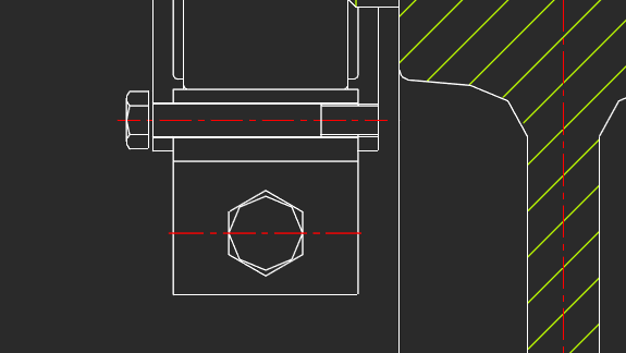
Designing bolted and riveted joints

Designing bolted and riveted joints


Mechanica offers flexibility in handling bolt and rivet functions:

  • Connect groups of parts with arbitrary thickness using bolts, screws, or studs
  • Connect parts of arbitrary thickness with rivets displayed in regular and high accuracy, made of hollow and semi-hollow rivets
  • Display simplified fasteners in joints
  • Generate patterns of bolts and rivets in joints
BOM-tools

BOM tools


Mechanica’s BOM tools create bills of material of parts linked to drawings. BOM tables can contain the following items:

  • Itemized specification numbers
  • Electrical specifications
  • Automatic receipt of specifications
  • Custom specifications

Other important features

Dimension styles


Mechanica supports dimension styles, which are named collection of dimension settings that control the appearance of dimensions, such as the arrowhead, the text placement, and display of tolerances. It includes styles preset for a number of local and international standards.

Detail views with automatic updates


Mechanica generates detail views as objects that are updated by the MCREGEN command when the source model changes. When at least part of a scaled object falls into the view frame, then its scale is applied to the entire detail view.

MechWizard parameterizer


Mechanica’s MechWizard guides users through advanced functions:

  • Overlaying assembly and parametric dependencies on objects
  • 'Behavior training' of standard parts
  • Modification of database elements
  • Custom database elements

Calculation wizard


Mechanica’s powerful engineering calculators handle gear strengths, complex cross-sections of geometric properties with arbitrary axes, fasteners, bearing life at given load conditions, and more. Results of calculations are generated automatically as reports that show all formulas and ISO references used for the calculations.

Tutorials

nanoCAD 22 with Mechanica module

How to Work with sheet metal in nanoCAD Mechanica

How we can use constraint in nanoCAD Mechanica

How to use table in nanoCAD Mechanica

What's new in nanoCAD mechanica Download nanoCAD mechanica nanoCAD mechanica tutorial Frequently asked question